RIDGID TS3650 manual Raise blade guard. C. Loosen insert screw

Page 43

.SP6498 Belt Drive Saw 05/03 7/15/03 7:04 AM Page 43

2.Elevation Handwheel...elevates or lowers the blade. Turn clockwise to elevate, counterclockwise to lower.

3.Elevation Lock Knob...locks the blade at the desired height. To loosen, turn counterclockwise. To tighten, turn clockwise.

4Bevel Handwheel...tilts the blade for bevel cutting. Turn clockwise to tilt toward left, counterclockwise to tilt toward right.

When the blade is tilted to the left as far as it will go, it should be at 45° to the table and the bevel pointer should point 45°.

NOTE: There are limit stops inside the saw which prevent the blade from tilting beyond 45° to the left and 90° to the right. (See “Adjustments and Align- ments” section “Blade Tilt, or Square- ness of Blade to Table”).

5.Bevel Lock Handle...locks the blade in the desired tilt position. To loosen, turn counterclockwise. Push handle in and turn it to another position if necessary in order to tighten or loosen.

IMPORTANT: Be sure handle is hanging in the “DOWN” position before tilting blade. If it is pointing to the 1 o’clock position it may jam on underside of the table and bend the locking bolt.

6.Rip Fence...is locked in place by pushing the lock lever down until the lever rests on the stop. To move the fence, lift the lock lever and grasp the fence with one hand at the front.

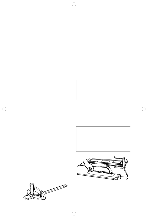
7.Miter Gauge...head is locked in position for cross cutting or mitering by tightening the lock knob. Always securely lock it when in use.

There are adjustable screw stops for the stop pin 0° and 45° right and left positions for conveniently setting the miter gauge to cut miters at these standard angles.

8.Blade Guard...must always be in place and working properly for all thru-sawing cuts. That is, all cuts where the blade cuts completely through the workpiece.

To remove the guard for special operations, loosen the thumbscrew and slide the guard off the rod. Do not disturb the setting of the rod.

When replacing the guard make sure the pin in the rod engages with the notch in the spreader support. Make sure the thumbscrew is tightened securely.

9.Table Insert...is removable for removing or installing blade or other cutting tools.

WARNING: To reduce the risk of injury from accidental start, turn switch “OFF” and remove plug from power source before removing insert.

A. Lower the blade below the table surface.

B. Raise blade guard. C. Loosen insert screw.

D. Lift insert from front end, and pull toward front of saw.

WARNING: Never operate saw without the proper insert in place. Use the table insert when sawing. Use the combination dado molding insert when using a dado or molding head.

43

Image 43
Contents TS3650 Table of Contents Safety Signal Words Before Using The Saw Safety Instructions For Table SawTo reduce the risk of injury from unexpected saw movement When Installing Or Moving The SawBefore Each Use Reduce the Risk of Dangerous EnvironmentInspect Your Blade Inspect your workpiece Dress for safetyPlan Ahead To Protect Your Eyes, Hands, Face and Ears Plan your workDon’t Force Tool Whenever Sawblade Is SpinningReduce the Risk of Accidental Starting Keep Children AwayAdditional Safety Instructions For Glossary of Terms for Woodworking Gum DadoFeatherboard FreehandPower Supply and Motor Specifications Motor Specifications and Electrical RequirementsGeneral Electrical Connections Volt, 60 Hz. Tool Information Changing Motor Voltage Motor Thermal Overload Protector Wire SizesUnpacking and Checking Contents Operators Manuals List of Loose Parts Part Name QtyLoose Parts AssemblyInstalling Bevel Handwheel Herc-U-Lift Caster Carton Description QtyAssembling Leg Stand Installing Elevation HandwheelMiter Gauge Rip Fence Storage Hook End Panel Screw Head Leg Mounting Your Saw Assembling Table Extensions Checking Table Insert To check for parallelism Minimum Clearance Rear Saw To check for squareness, 90 position Checking Blade Tilt, or Squareness of Blade to TableIf blade is square to table If blade is 45 to table To check for alignment, 45 PositionUpper Assembly Assembling Herc-U-Lift Caster System Assembly TipsLower Assembly Center Frames Equal Distance on Each Side Tighten All Nuts Operation of Herc-U-Lift Caster System Installing Front Rip Fence Guide Bar Installing Rear Fence Guide Bar Aligning Rip Fence Guide Bars Adjusting Rip Fence Guide Bars Installing ShimsInstalling Spacer Bar Rip Fence Lock Lever Adjustment Installing Blade Guard Adjusting Fence IndicatorAligning Blade Guard Mounting the Motor Installing Belt Guard Installing Belt10-32 Mounting Switch and End CapsSwitch Mounted on Left Side Mounting Switch on Right SideMounting Switch on Left Side Switch Mounted on Right SideGetting to Know Your Table Saw On-Off SwitchRaise blade guard. C. Loosen insert screw Plug From Power source outlet Switch OFF and remove plug From power source outlet beforeRemoving or installing sawblade Turn Switch OFF and removeStorage Hooks Conveniently holds rip fence Miter gauge when not in useSawdust Ejection Port Remove the Existing Table Insert Installing Zero Clearance Insert/SawbladeOperation Tips Installing Zero Clearance Insert/Dado BladesInspect your saw Safety Instructions for Basic Saw OperationsBefore Each Use Plan your cut Inspect your work areaPlan your work Inspect your workpieceReduce the Risk of Accidental Starting Work Feed Devices Attaching Wood Face Board Making the base Push BlockMaking the side Auxiliary FenceMaking the handle Putting it TogetherWork Support for Material over Wide Install extensionCrosscutting Additional Safety Instructions for CrosscuttingUsing the Miter Gauge Basic Saw OperationsRepetitive Crosscutting Bevel Crosscutting Miter CrosscuttingCompound Crosscutting Additional Safety Instructions for Rip Cuts Using the Rip FenceOnce the trailing end is on the table RippingBevel Ripping Narrow Work Using Featherboards for Non Thru-Sawing Using Featherboards for Thru- SawingResawing Dadoing Using Carbide Tipped BladesPloughing and Molding RabbetingMolding Miter Gauge Adjusting Stop Screws AdjustmentsMaintaining Your Table Saw MaintenanceHerc-U-Lift Caster System Miter Gauge Hold Down AC1022 Ridgid Recommends the Following AccessoriesLubrication SKU No120V 240V Wiring Diagrams240V Troubleshooting Troubleshooting Troubleshooting SP6498 Belt Drive Saw 05/03 7/15/03 705 AM Catalog No. TS3650 Model No TS36500 Serial No RIDGID, INC