.SP6498 Belt Drive Saw 05/03 7/15/03 7:04 AM Page 14
Motor Specifications and Electrical Requirements (continued)
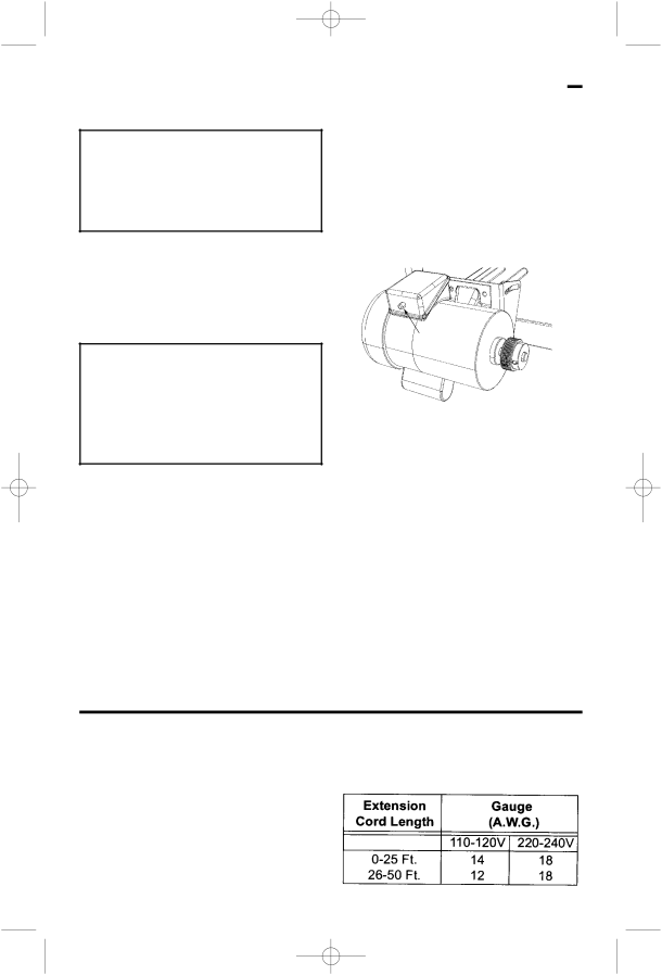
Motor Thermal Overload Protector
CAUTION: To reduce the risk of motor damage, this motor should be blown out or vacuumed frequently to prevent sawdust buildup which will interfere with normal motor ventilation.
Your saw is equipped with a
WARNING: To reduce the risk of thrown objects or blade contact from unexpected starting. If the protector stops the saw motor, immediately turn the saw switch “OFF”, remove the key and allow motor time to cool.
1.After cooling to a safe operating temperature, the overload protector can be reset by pushing the red button on the junction box of the motor. If the red button will not click into place immediately, the motor is still too hot and must be allowed to cool for a while longer.
The time required for the motor to cool may be equal to the length of time the saw was used before the thermal overload protector opened. NOTE: An audible click will indicate the protector is reset, push hard to hear the click.
2.As soon as the red button is reset, the saw may be started and operated normally.
3.Frequent “blowing” of fuses or tripping of circuit breakers may result if:
a. Motor is overloaded - Overloading can occur if you feed too rapidly or if saw is misaligned.
b. Motor circuit is fused differently from recommendations - Always follow instructions for the proper fuse/ breaker. Do not use a fuse/breaker of greater capacity without consulting a qualified electrician.
Manual Reset
Button
c. Low voltage - Although the motor is designed for operation on the voltage and frequency specified on motor nameplate, normal loads will be handled safely on voltage not more than 10% above or below the nameplate voltage. Heavy loads, however, require that voltage at motor terminals equals the voltage specified on nameplate.
4.Most motor troubles may be traced to loose or incorrect connections, overloading, reduced input voltage (such as small size wire in the supply circuit) or to overly long supply circuit wire. Always check the connections, the load and the supply circuit whenever motor fails to perform satisfactorily. Check wire sizes and length with the Wire Size Chart below.
Wire Sizes
NOTE: Make sure the proper extension cord is used and is in good condition. The use of any extension cord will cause some loss of power. To keep this to a minimum and to prevent overheating and motor
Use only
14 |
| 16 |
12 |
| 14 |
14