HP RP5 5810 manual

Page 57

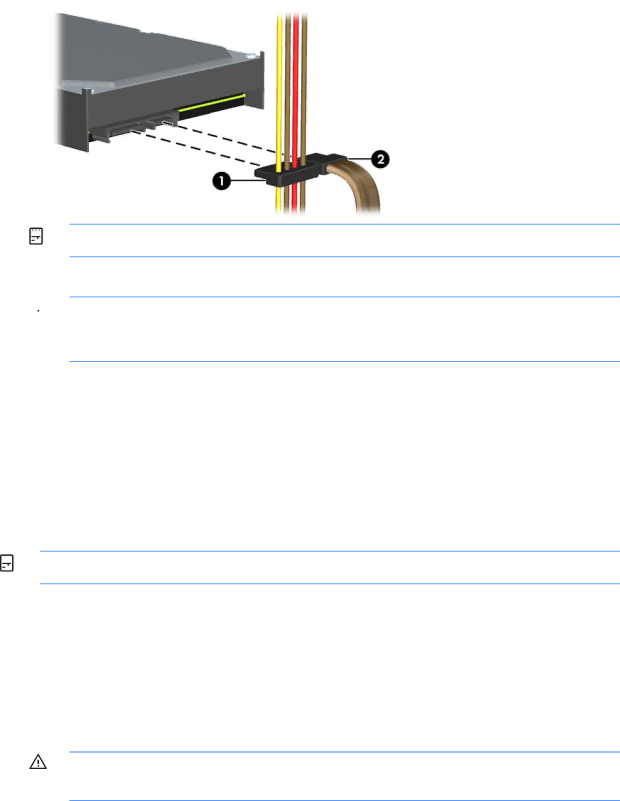
4.Connect the power cable (1) and data cable (2) to the back of the hard drive. Connect the other end of the data cable to the light blue SATA connector on the system board labeled SATA1.

Figure 2-61Connecting the Secondary Hard Drive Power and Data Cables

NOTE: Refer to System Board Drive Connections on page 41 for an illustration of the system board drive connectors.

5.Route the data cable through the cable guides.

CAUTION: There are two cable guides that keep the data cable from being pinched by the drive cage when raising or lowering it. One is located on the bottom side of the drive cage. The other is located on the chassis frame under the drive cage. Ensure that the data cable is routed through these guides.

6.Replace the optical drive.

7.Replace the access panel.

8.If the computer was on a stand, replace the stand.

9.Reconnect the power cord and any external devices, then turn on the computer.

10.Lock any security devices that were disengaged when the access panel was removed.

Removing and Replacing the Primary 3.5-inch Internal Hard Drive

NOTE: Before you remove the old hard drive, be sure to back up the data from the old hard drive so that you can transfer the data to the new hard drive.

The preinstalled 3.5-inch primary hard drive is located under the power supply. To remove and replace the primary hard drive:

1.Remove/disengage any security devices that prohibit opening the computer.

2.Remove all removable media, such as optical discs or USB flash drives, from the computer.

3.Turn off the computer properly through the operating system, then turn off any external devices.

4.Disconnect the power cord from the power outlet and disconnect any external devices.

CAUTION: Regardless of the power-on state, voltage is always present on the system board as long as the system is plugged into an active AC outlet. You must disconnect the power cord to avoid damage to the internal components of the computer.

Installing and Removing Drives 51

Image 57
Contents Hardware Reference Guide Product Notice About This Book Iv About This Book Table of contents Preventing Electrostatic Damage Grounding Methods Standard Configuration Features Product FeaturesFront Panel Components Drive configuration may vary by model2Rear Panel Components Rear Panel ComponentsChanging from Desktop to Tower Configuration Installing the Optional Port Cover 7Cable Routing Serial Number LocationHardware Upgrades Replacing the Computer Access Panel Removing the Computer Access PanelRemoving the Front Bezel 5Installing the Optical Drive Bezel Hardware Upgrades Installing an Optical Drive BezelReplacing the Front Bezel Removing a Bezel BlankInstalling Additional Memory DIMMsDDR3-SDRAM DIMMs 1DIMM Socket Locations Populating Dimm SocketsInstalling DIMMs Page Page 2System Board Expansion Slot Locations Installing a Half-Height Expansion Card1324-volt and 12-volt Powered USB Connectors Installing a 12-Volt Powered USB Expansion CardPage Page Page Page Page Installing a Second DisplayPort Expansion Card Page Page 4Riser Card Configurations Installing a Full-Height Expansion Card25Powered Serial Ports Installing a Powered Serial Port Expansion CardPage Page Close the expansion card retention latch Replacing the Riser Card Configuring Powered Serial PortsPage 35Removing the Lower Expansion Slot Cover Hardware Upgrades 37Removing the Riser Card Bracket Replacing the Riser Card 39Installing the Riser Card Hardware Upgrades Page Close the expansion card retention latch Drive Positions Installing and Removing Drives45Extra Guide Screw Locations 8System Board Drive Connections System Board Drive ConnectionsRemoving an Optical Drive from the 5.25-inch Drive Bay Page 50Removing the 5.25-inch Drive Installing an Optical Drive into the 5.25-inch Drive BayPage Page Page Removing a Secondary Hard Drive from the 3.5-inch Drive Bay Page 60Installing a Secondary Hard Drive Hardware Upgrades Page 63Raising the Power Supply Hardware Upgrades Page Page 67Installing the Hard Drive Installing and Removing Drives Page Type Replacing the Battery69Removing and Replacing a Coin Cell Battery Type HP Keyed Cable Lock Installing a Security LockPadlock HP Business PC Security Lock Page Page Page Front Bezel Security Page Optional Integration Tray and Accessories Page Grounding Methods Preventing Electrostatic DamageComputer Operating Guidelines and Routine Care Cleaning Optical Drive PrecautionsSafety Shipping PreparationIndex USB