HP RP5 5810 manual HP Business PC Security Lock

Page 67

HP Business PC Security Lock

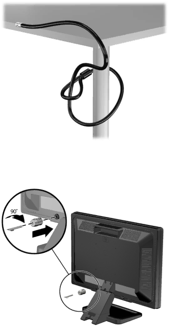
1.Fasten the security cable by looping it around a stationary object. Figure A-3Securing the Cable to a Fixed Object

2.Insert the cable lock into the cable lock slot on the back of the monitor and secure the lock to the monitor by inserting the key into the key hole on the rear of the lock and rotating the key 90 degrees.

Figure A-4Installing the Cable Lock on the Monitor

Installing a Security Lock 61

Image 67
Contents Hardware Reference Guide Product Notice About This Book Iv About This Book Table of contents Preventing Electrostatic Damage Grounding Methods Standard Configuration Features Product FeaturesFront Panel Components Drive configuration may vary by model2Rear Panel Components Rear Panel ComponentsChanging from Desktop to Tower Configuration Installing the Optional Port Cover 7Cable Routing Serial Number LocationHardware Upgrades Replacing the Computer Access Panel Removing the Computer Access PanelRemoving the Front Bezel 5Installing the Optical Drive Bezel Hardware Upgrades Installing an Optical Drive BezelReplacing the Front Bezel Removing a Bezel BlankDIMMs Installing Additional MemoryDDR3-SDRAM DIMMs 1DIMM Socket Locations Populating Dimm SocketsInstalling DIMMs Page Page 2System Board Expansion Slot Locations Installing a Half-Height Expansion Card1324-volt and 12-volt Powered USB Connectors Installing a 12-Volt Powered USB Expansion CardPage Page Page Page Page Installing a Second DisplayPort Expansion Card Page Page 4Riser Card Configurations Installing a Full-Height Expansion Card25Powered Serial Ports Installing a Powered Serial Port Expansion CardPage Page Close the expansion card retention latch Replacing the Riser Card Configuring Powered Serial PortsPage 35Removing the Lower Expansion Slot Cover Hardware Upgrades 37Removing the Riser Card Bracket Replacing the Riser Card 39Installing the Riser Card Hardware Upgrades Page Close the expansion card retention latch Drive Positions Installing and Removing Drives45Extra Guide Screw Locations 8System Board Drive Connections System Board Drive ConnectionsRemoving an Optical Drive from the 5.25-inch Drive Bay Page 50Removing the 5.25-inch Drive Installing an Optical Drive into the 5.25-inch Drive BayPage Page Page Removing a Secondary Hard Drive from the 3.5-inch Drive Bay Page 60Installing a Secondary Hard Drive Hardware Upgrades Page 63Raising the Power Supply Hardware Upgrades Page Page 67Installing the Hard Drive Installing and Removing Drives Page Type Replacing the Battery 69Removing and Replacing a Coin Cell Battery Type HP Keyed Cable Lock Installing a Security LockPadlock HP Business PC Security Lock Page Page Page Front Bezel Security Page Optional Integration Tray and Accessories Page Grounding Methods Preventing Electrostatic DamageComputer Operating Guidelines and Routine Care Shipping Preparation Optical Drive PrecautionsCleaning SafetyIndex USB