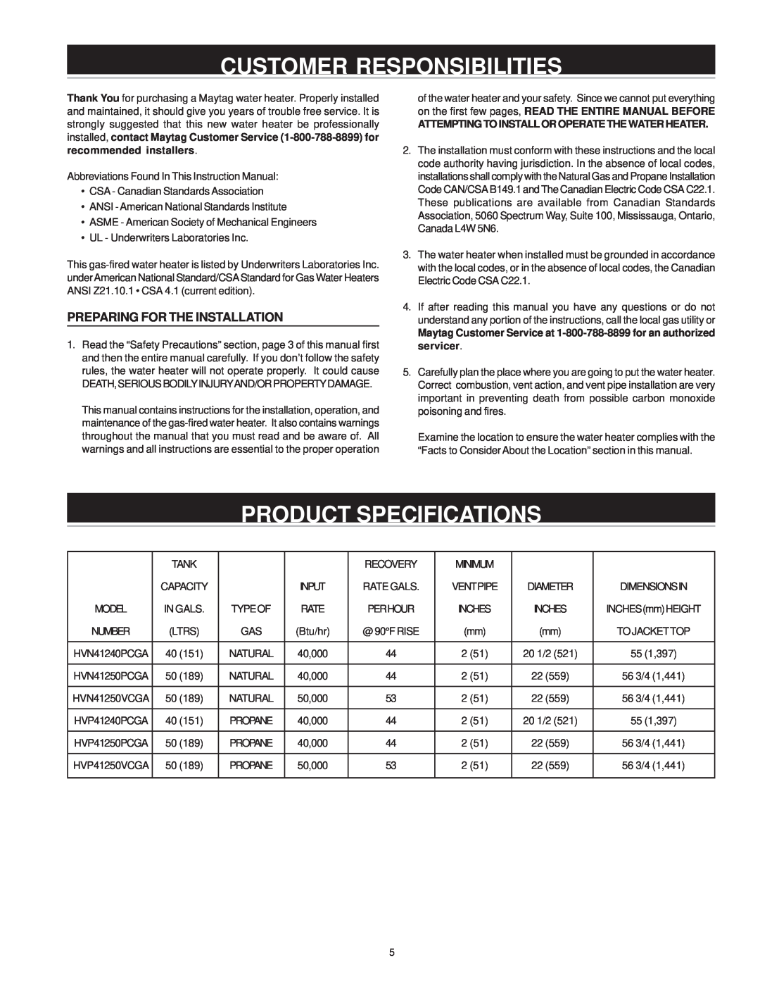
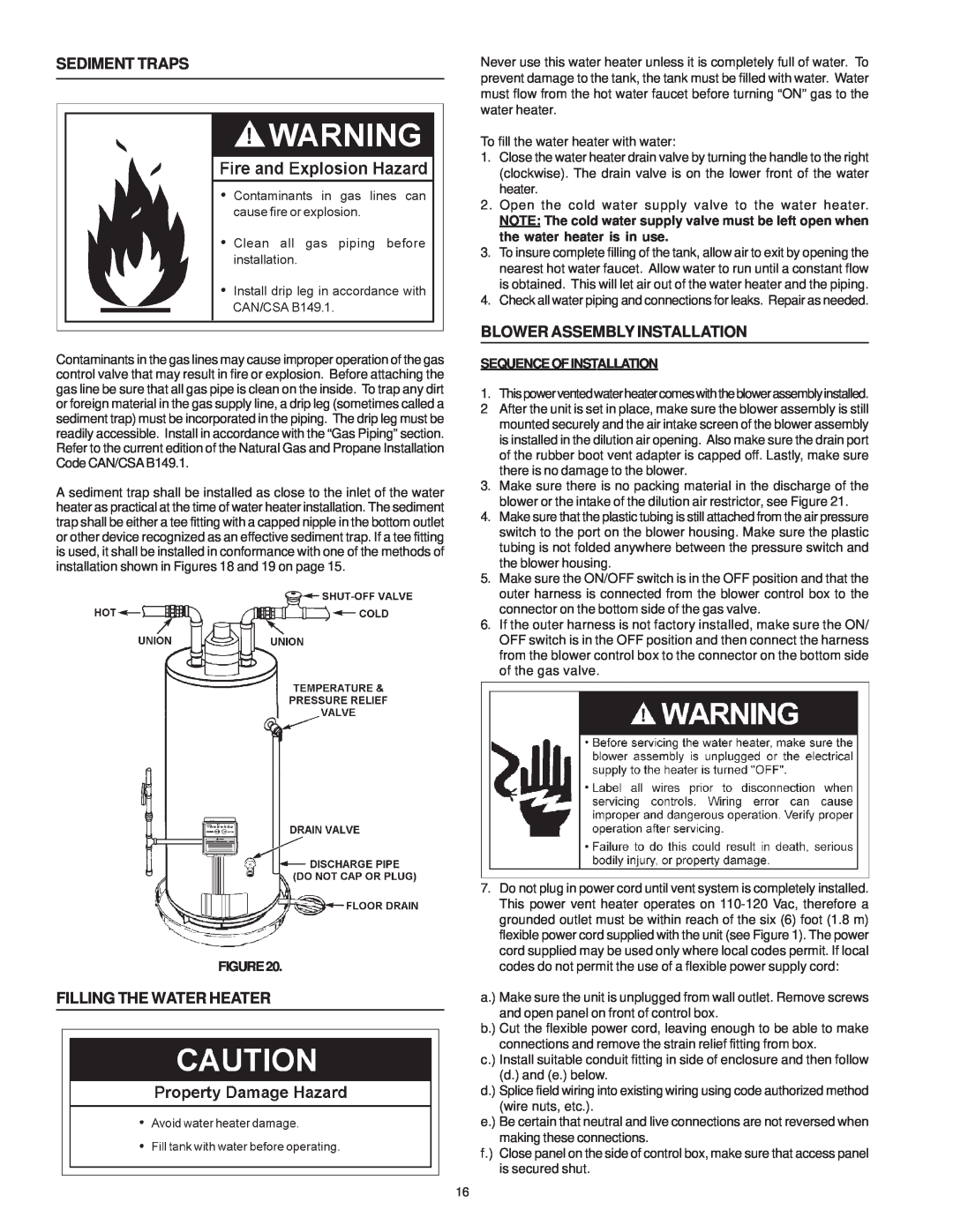
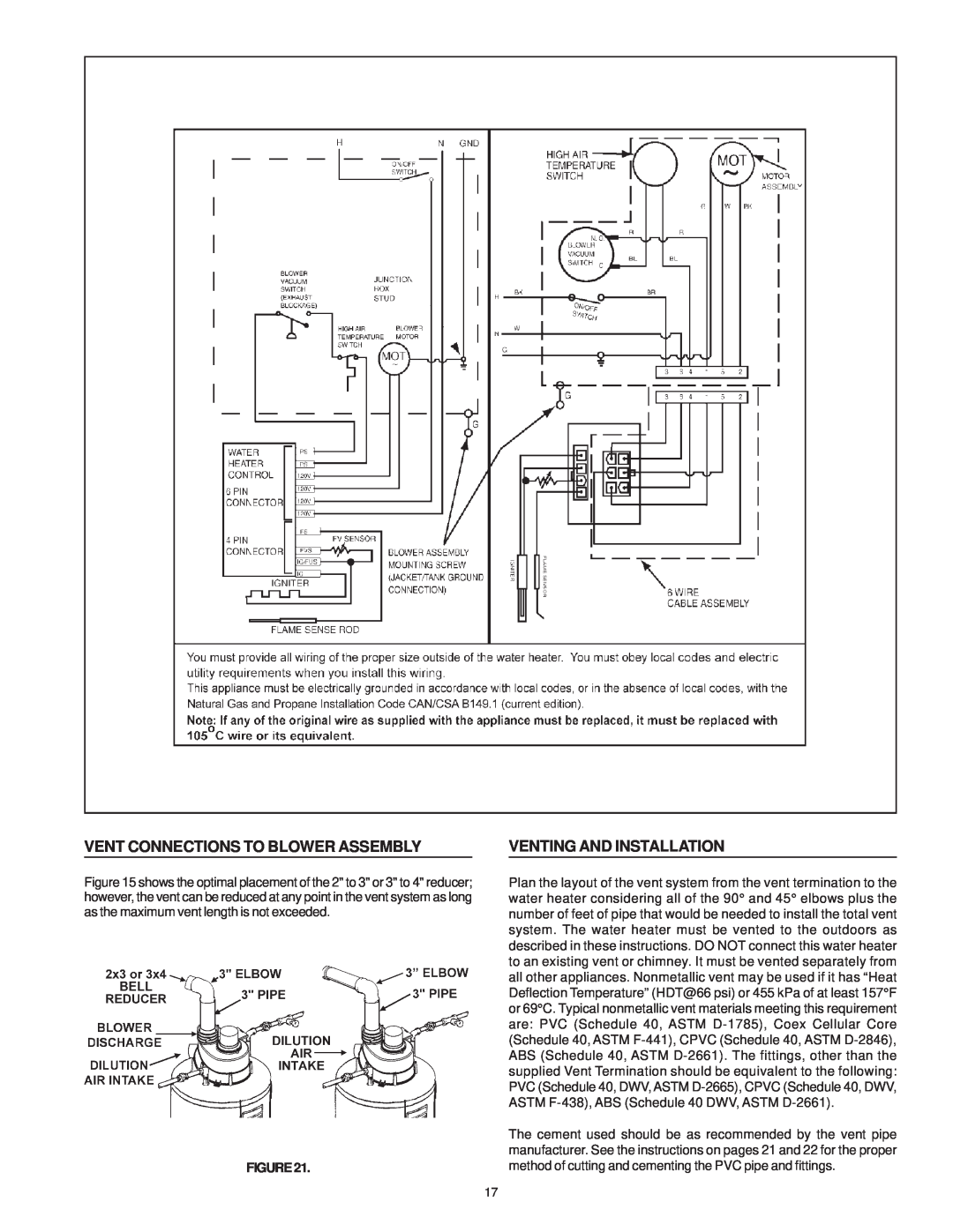
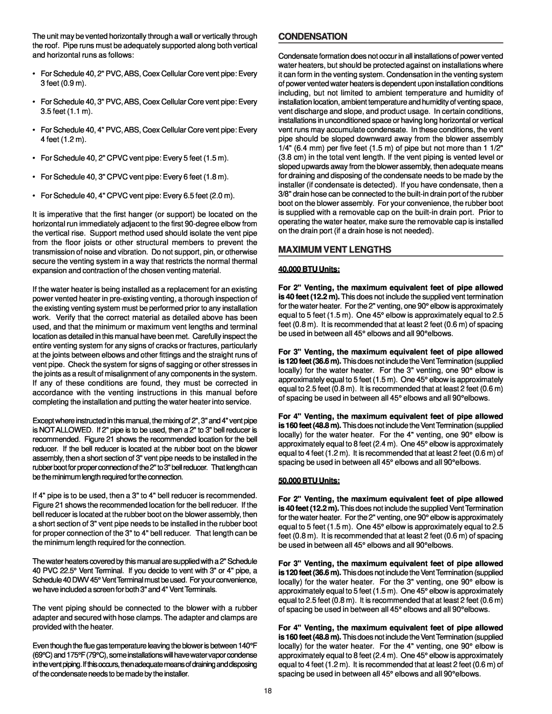
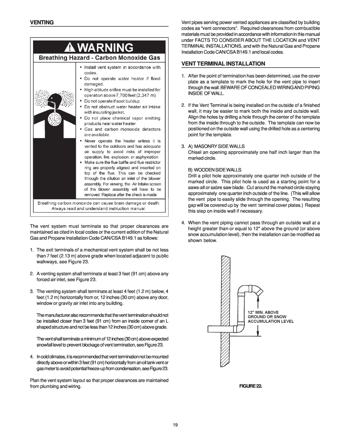
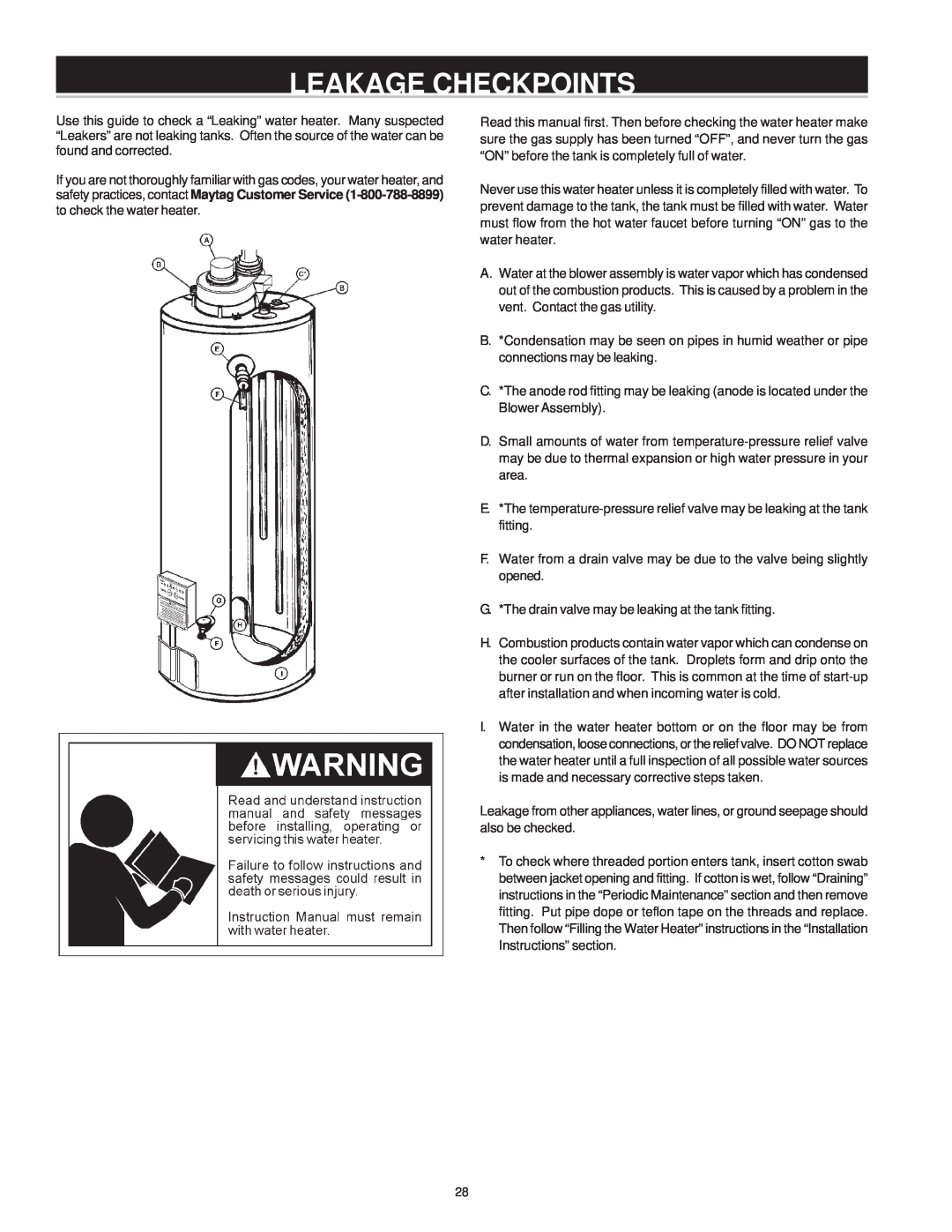
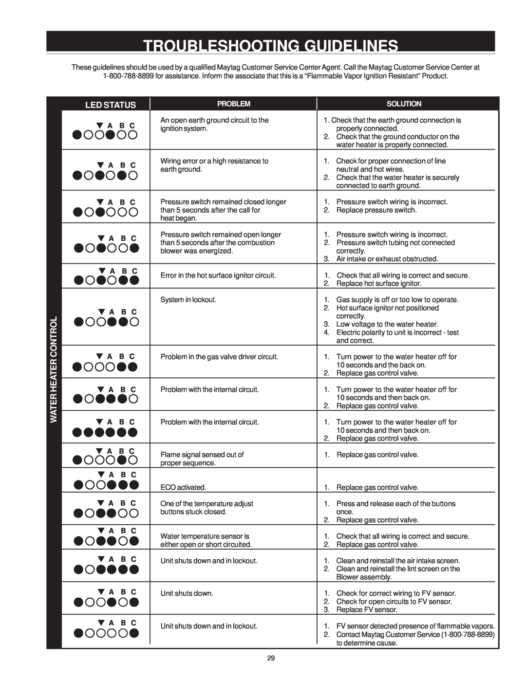
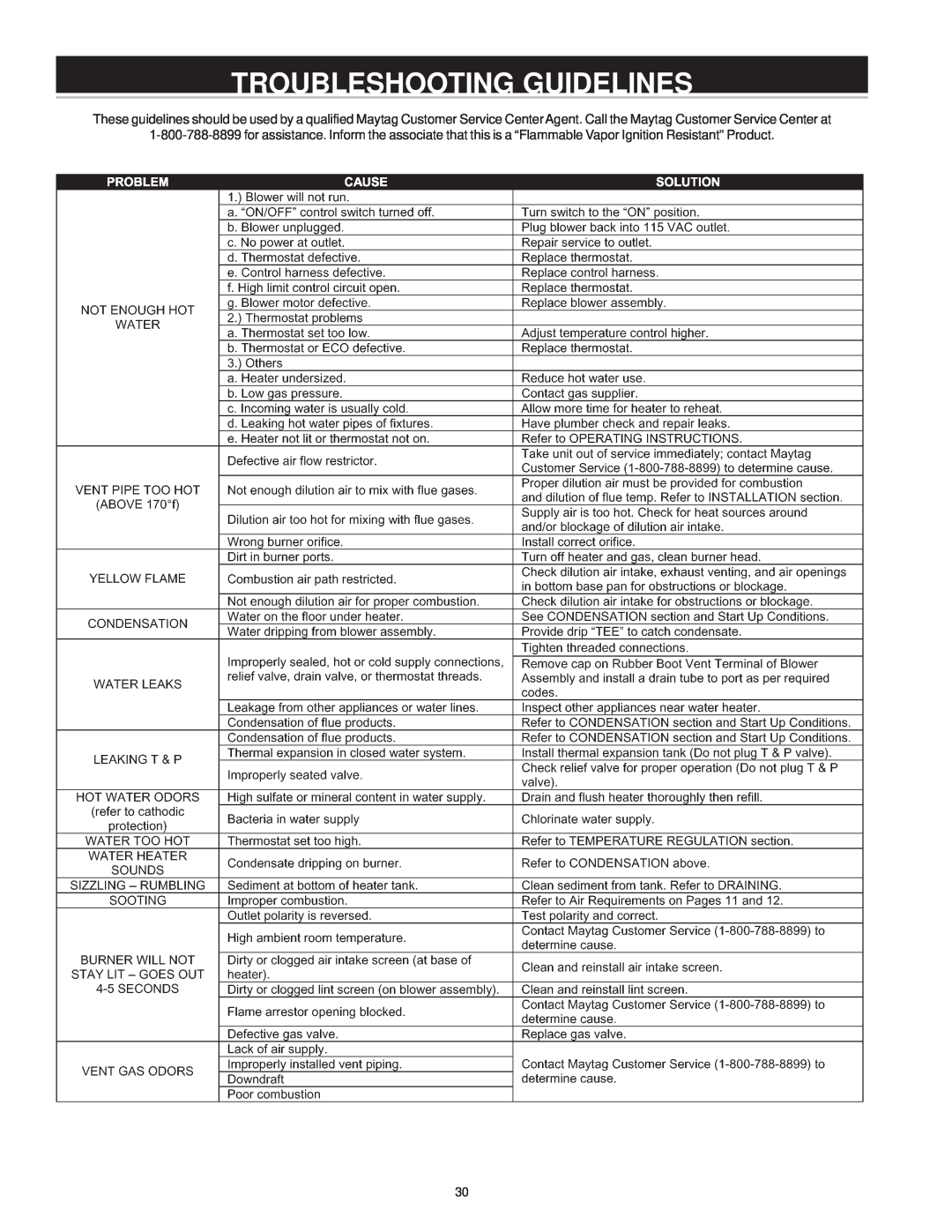
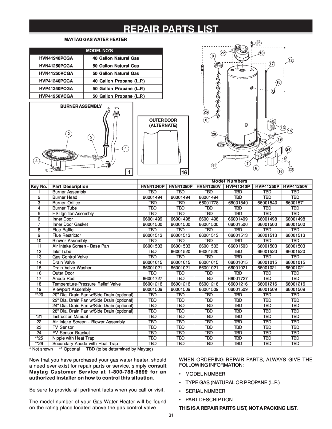
Maytag HVN41240PCGA, HVN41250VCGA, HVN41250PCGA manual Typical Installation, Mixing Valve Usage

Page 8
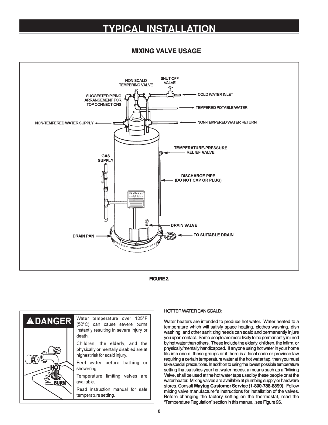
MIXING VALVE USAGE

TYPICAL INSTALLATION

MIXING VALVE USAGE

FIGURE2.

HOTTERWATERCANSCALD:

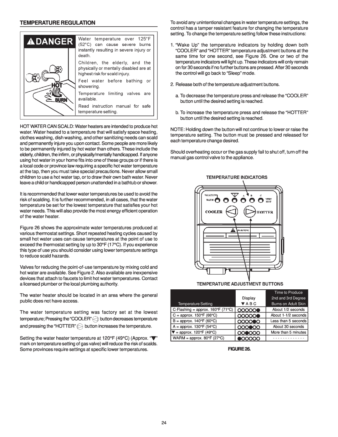
Water heaters are intended to produce hot water. Water heated to a temperature which will satisfy space heating, clothes washing, dish washing, and other sanitizing needs can scald and permanently injure you upon contact. Some people are more likely to be permanently injured by hot water than others. These include the elderly, children, the infirm, or physically/mentally handicapped. If anyone using hot water in your home fits into one of these groups or if there is a local code or province law requiring a certain temperature water at the hot water tap, then you must take special precautions. In addition to using the lowest possible temperature setting that satisfies your hot water needs, a means such as a *Mixing Valve, shall be used at the hot water taps used by these people or at the water heater. Mixing valves are available at plumbing supply or hardware stores. Consult Maytag Customer Service (1-800-788-8899). Follow mixing valve manufacturer’s instructions for installation of the valves. Before changing the factory setting on the thermostat, read the “Temperature Regulation” section in this manual, see Figure 26.

8

Image 8
Contents POWER VENT GAS WATER HEATER USER’S GUIDE Series TwelveSAFE INSTALLATION, USE AND SERVICE IMPORTANT DEFINITIONSSAFETY PRECAUTIONS TABLE OF CONTENTS PREPARING FOR THE INSTALLATION PRODUCT SPECIFICATIONSCUSTOMER RESPONSIBILITIES MATERIALS AND BASIC TOOLS NEEDED AccessoriesAdditional Tools Needed When Sweat Soldering ToolsTYPICAL INSTALLATION GET TO KNOW YOUR WATER HEATER - GAS MODELSGAS MODELS WITH HOT SURFACE IGNITION 2, 3 OR 4 PVC VENT CAPABILITYFIGURE2 TYPICAL INSTALLATIONMIXING VALVE USAGE INSTALLATION INSTRUCTIONS Removing the Old Water HeaterFACTS TO CONSIDER ABOUT THE LOCATION FIGURE9INSULATION BLANKETS FIGURE12 FIGURE13FIGURE14 FIGURE15WATER PIPING FIGURE17 TEMPERATURE-PRESSURERELIEF VALVET & P Valve and Pipe Insulation if supplied FIGURE 18. GAS PIPING WITH FLEXIBLECONNECTOR GAS PIPINGBLOWER ASSEMBLY INSTALLATION SEQUENCEOFINSTALLATIONSEDIMENT TRAPS FILLING THE WATER HEATERFIGURE21 VENT CONNECTIONS TO BLOWER ASSEMBLYVENTING AND INSTALLATION CONDENSATION MAXIMUM VENT LENGTHS40,000 BTU Units 50,000 BTU UnitsFIGURE22 VENT TERMINAL INSTALLATIONVENTING VERTICAL VENT THROUGH ROOF VERTICAL VENT RESTRICTIONSFIGURE23 FIGURE24AND CEMENT APPLICATIONS VENT PIPE PREPARATIONRECOMMENDED BRUSH* SIZE FOR PRIMER D.Inspection, cleaning, priming STEPE F. Joint assemblySTEPF G. Cleanup and joint movement B.DeburringOPERATING INSTRUCTIONS FOR YOUR SAFETY READ BEFORE OPERATINGOPERATING INSTRUCTIONS TO TURN OFF GAS TO APPLIANCETEMPERATURE REGULATION FIGURE26OPERATIONAL CONDITIONS FOR YOUR INFORMATIONSTART UP CONDITIONS SERVICE AND ADJUSTMENT BURNER CLEANINGVENTING SYSTEM INSPECTION BURNER OPERATION AND INSPECTIONDRAIN VALVE WASHER REPLACEMENT SERVICEANODE ROD INSPECTION DRAININGLEAKAGE CHECKPOINTS TROUBLESHOOTING GUIDELINES PROBLEMSOLUTION WATER HEATER CONTROLTROUBLESHOOTING GUIDELINES These guidelines should be used by a qualified Maytag Customer Service Center Agent. Call the Maytag Customer Service Center atREPAIR PARTS LIST THIS IS A REPAIR PARTS LIST, NOT A PACKING LISTWARRANTY FULL ONE YEAR WARRANTYLIMITED PARTS WARRANTY LIMITED TANK WARRANTY AGAINST LEAKS