Heat & Glo LifeStyle BE-41 manual Continue Adding Vent Components, Install Support Brackets

Page 19

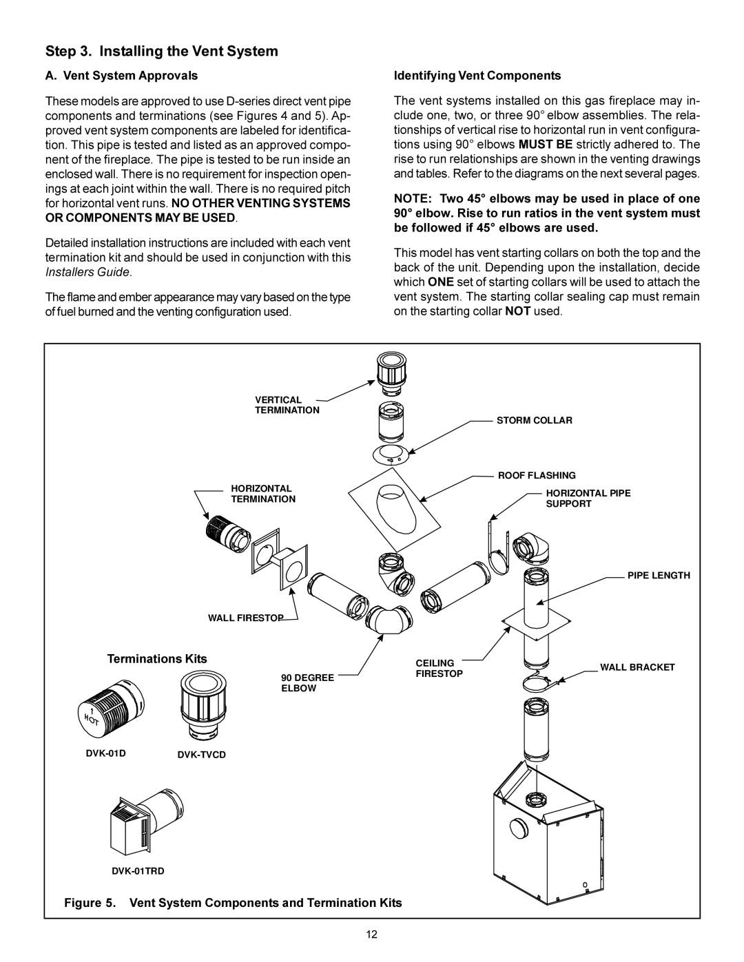
2.Continue Adding Vent Components

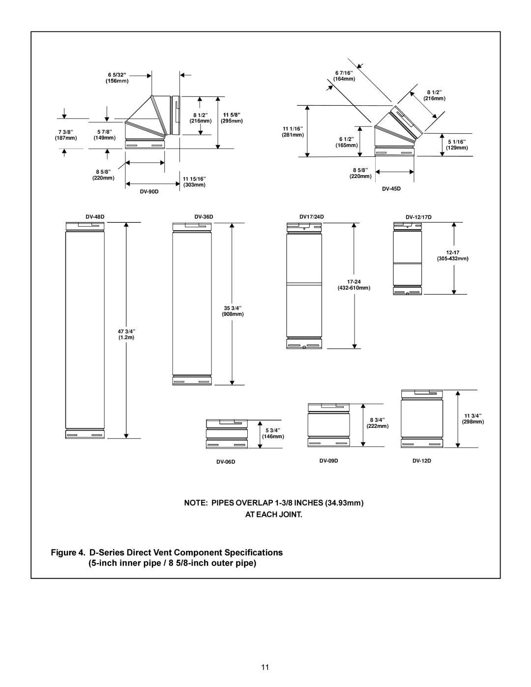
Continue adding vent components, locking each succeed- ing component into place.

Ensure that each succeeding vent component is secure- ly fitted and locked into the preceding component in the vent system.

90° elbows may be installed and rotated to any point around the preceding component’s vertical axis. If an el- bow does not end up in a locked position with the pre- ceding component, attach with a minimum of two (2) sheet metal screws.

Figure 17. Adding Venting Components

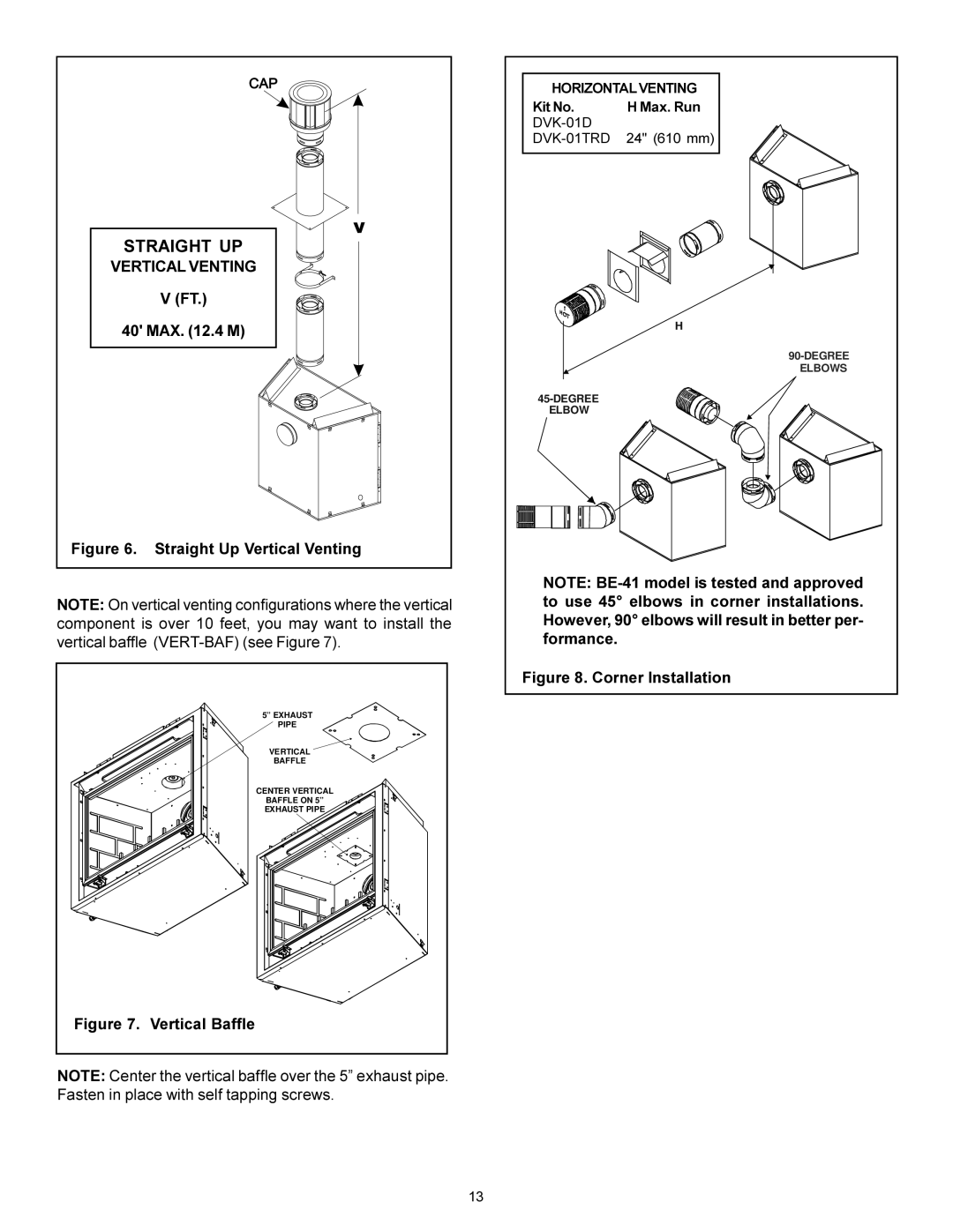
3. Install Support Brackets

For Horizontal Runs - The vent system must be supported every five (5) feet of horizontal run by a horizontal pipe support.

To install support brackets for horizontal runs:

Place the pipe supports around the vent pipe.

Nail the pipe supports to the framing members.

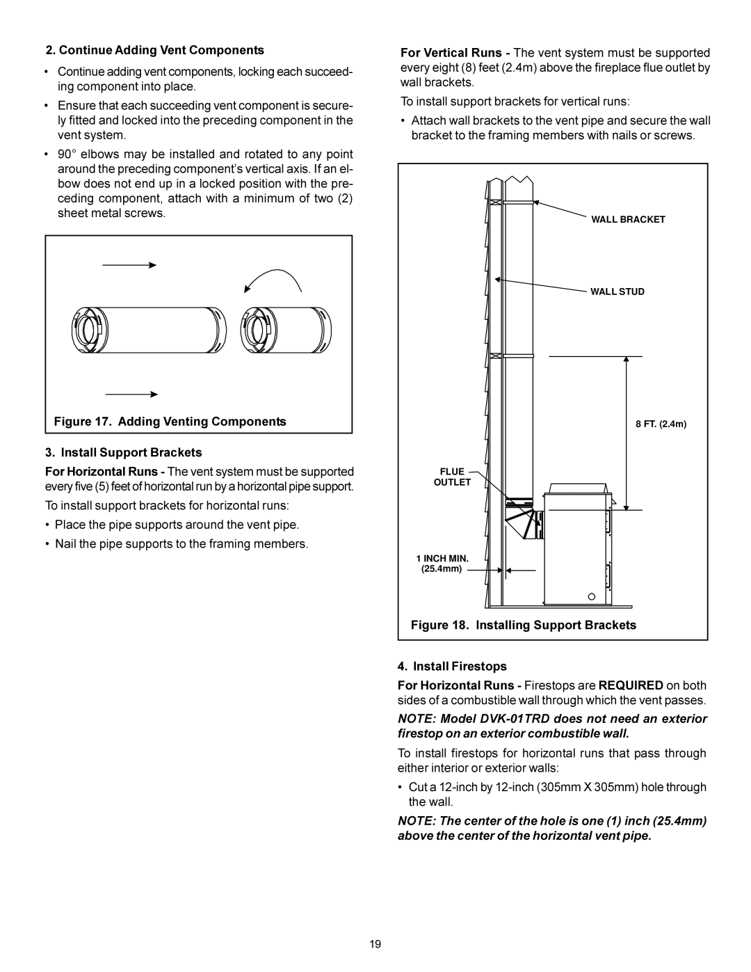
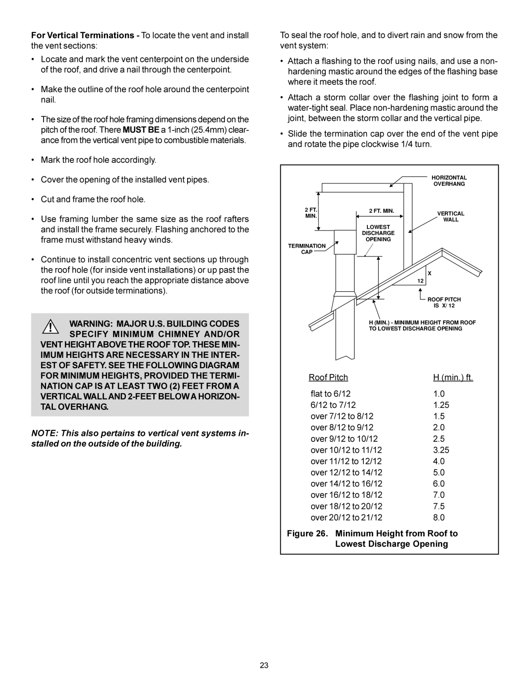
For Vertical Runs - The vent system must be supported every eight (8) feet (2.4m) above the fireplace flue outlet by wall brackets.

To install support brackets for vertical runs:

Attach wall brackets to the vent pipe and secure the wall bracket to the framing members with nails or screws.

WALL BRACKET

WALL STUD

8 FT. (2.4m)

FLUE

OUTLET

1 INCH MIN. (25.4mm)

Figure 18. Installing Support Brackets

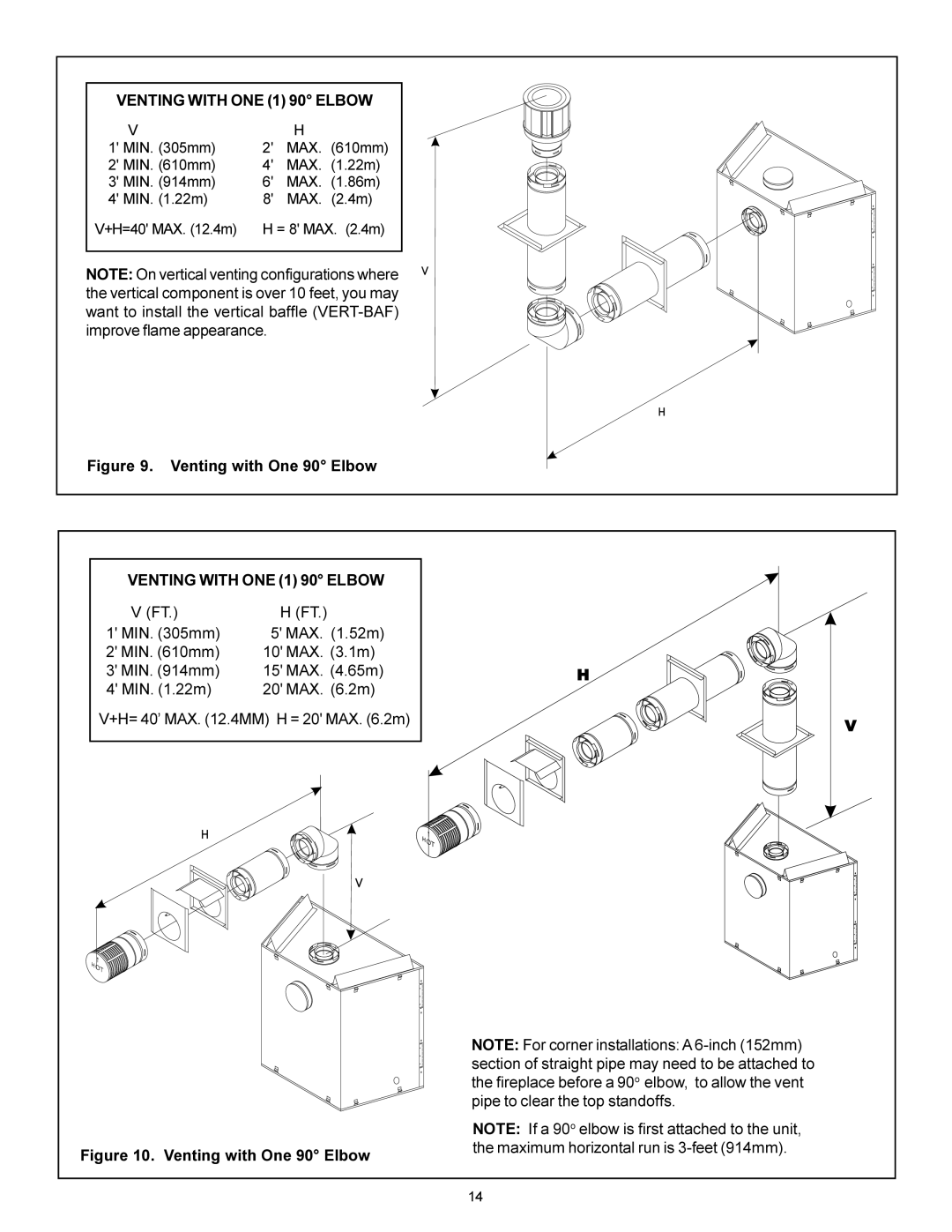
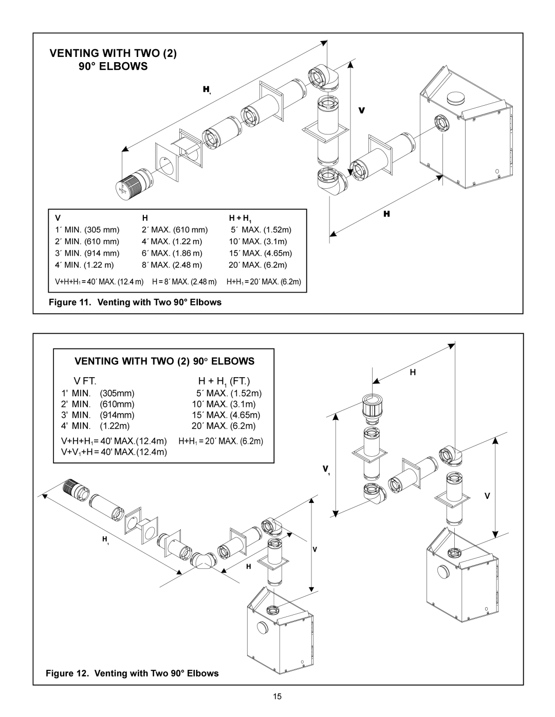
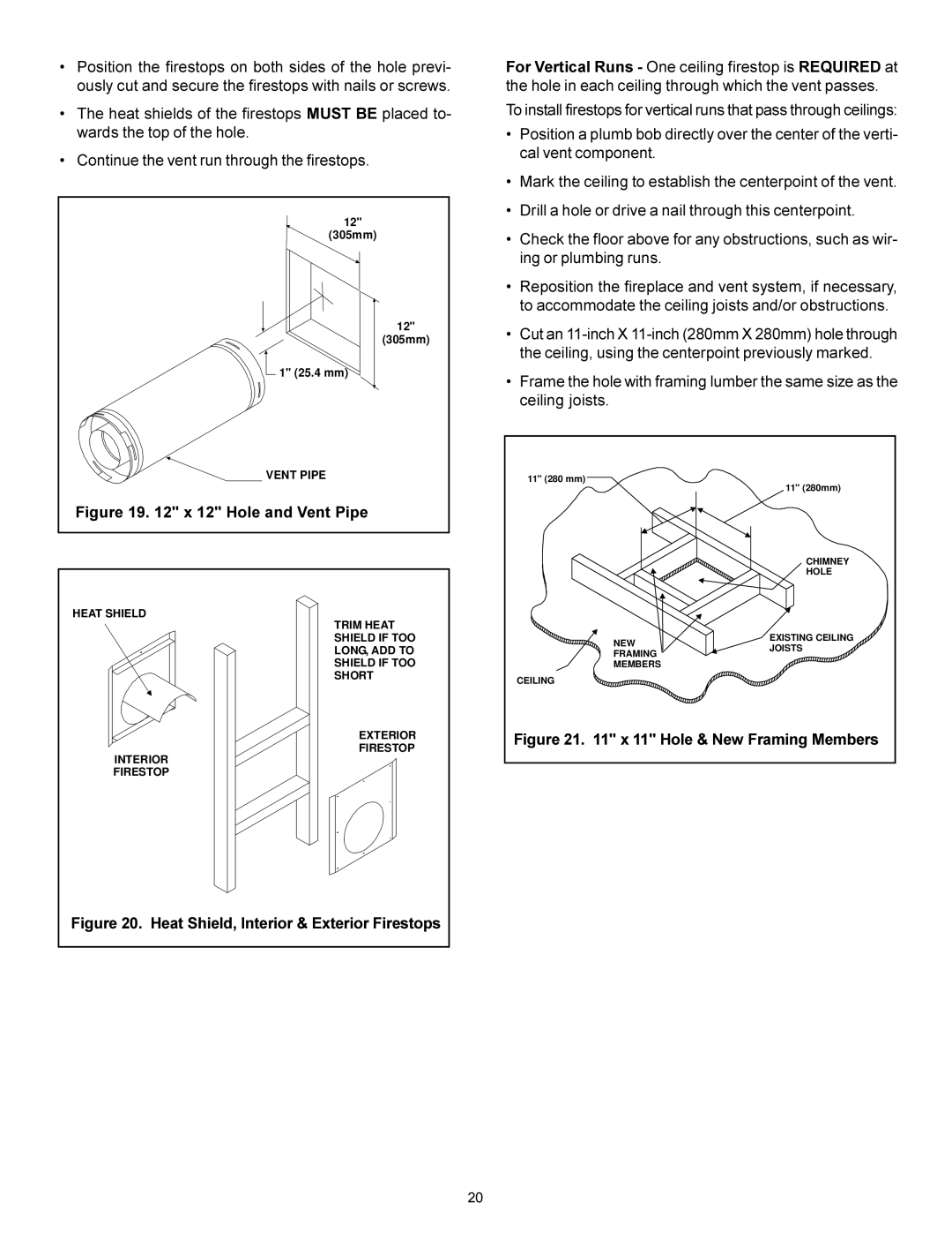
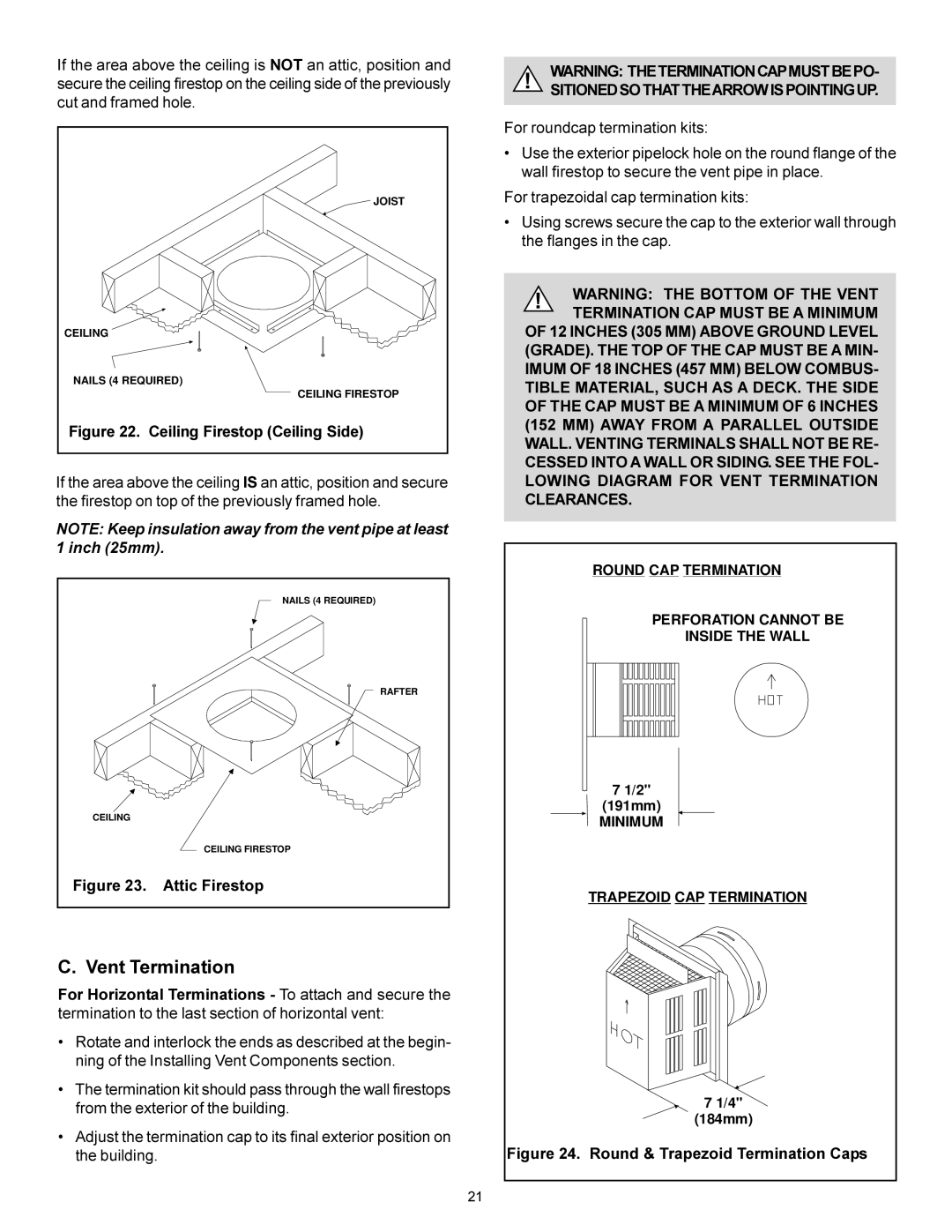
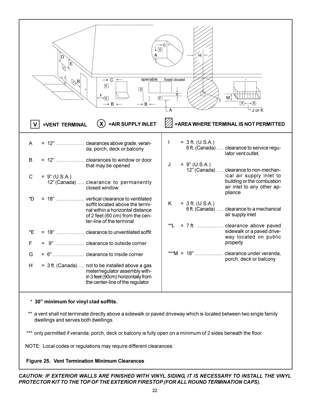
4. Install Firestops

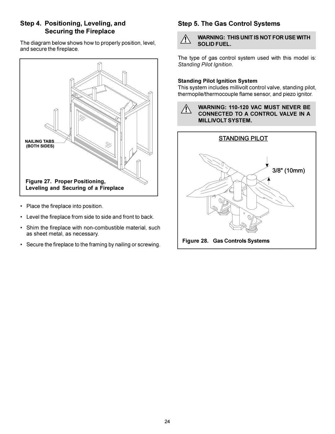
For Horizontal Runs - Firestops are REQUIRED on both sides of a combustible wall through which the vent passes.

NOTE: Model DVK-01TRD does not need an exterior firestop on an exterior combustible wall.

To install firestops for horizontal runs that pass through either interior or exterior walls:

Cut a 12-inch by 12-inch (305mm X 305mm) hole through the wall.

NOTE: The center of the hole is one (1) inch (25.4mm) above the center of the horizontal vent pipe.

19
Image 19
Contents What to do if you smell gas Installers GuideSafety and Warning Information Table of Contents Service Parts LOGS-BE41 BE-41 Service Parts List / Liste des pièces de rechangeCertification High Altitude InstallationsInstallation Codes Appliance CertificationIntroducing the Heat-N-Glo Gas Fireplaces Pre-install PreparationANY Such Action MAY Possibly Cause a Fire Hazard GAS Line AccessLocating the Fireplace Fireplace Dimensions, LocationsSpace Requirements Clearance Requirements Framing the Fireplace Framing DimensionsAT Each Joint Terminations Kits Installing the Vent SystemVent System Approvals Identifying Vent ComponentsMAX .4 M Vertical VentingStraight Up Vertical Venting Venting with One 90 Elbow Venting with ONE 1 90 ElbowVenting with TWO Elbows Venting with three 90 elbows Venting with Three 3 90 Elbows+ H 1 FT Attach the First Vent Component to the Starting Collars Installing Vent ComponentsVenting Out the Rear Vent Venting Out the Top VentContinue Adding Vent Components Install Support Brackets12 Hole and Vent Pipe Attic Firestop Vent TerminationMinimum for vinyl clad soffits =VENT Terminal =AIR Supply InletMinimum Height from Roof to Lowest Discharge Opening Standing Pilot Ignition System Positioning, Leveling, Securing the FireplaceGas Control Systems Leveling and Securing of a FireplaceGas Pressure Requirements Gas Supply LineRemote Wall Switch Wiring the FireplaceFor Standing Pilot Ignition Wiring Appliance Requirements Optional AccessoriesHearth Extensions Installing Trim, Logs, and Ember MaterialInstalling the Trim FinishingPositioning the Logs BeforeLog Placement Tabs Tempered After the InstallationBefore Lighting the Fireplace Lighting the FireplaceImportant Turn OFF the GAS Before Servicing Your Fireplace Fireplace Maintenance