Sterling 1200, 2000, SMS 850, 1500 manual Remaining Risks

Page 8

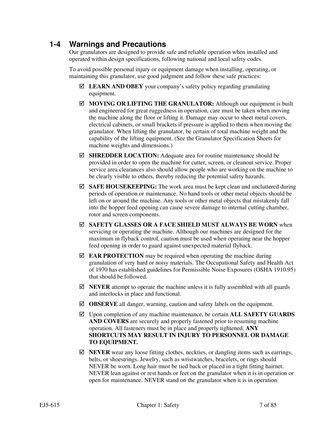
;ROTATION OF MOTORS: The correct rotating direction for the machine motor is clearly marked on the machine. Always check for proper rotation of motors. Incorrect rotation direction can cause severe damage.

;ELECTRICAL GROUNDING: All electrical equipment on the granulator must be grounded in accordance to all local codes and Article 250 of the National Electric Code.

;ALWAYS DISCONNECT AND LOCKOUT the main electrical power to the granulator before performing any service.

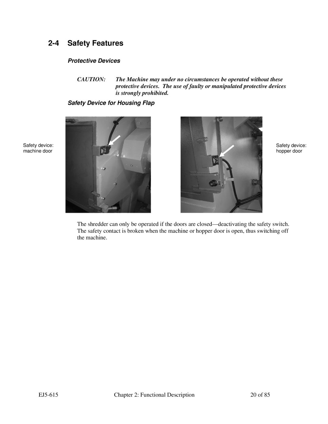
;SAFETY INTERLOCKS MUST NOT BE BYPASSED. The mechanical and electrical safety interlocks ensure the safety of personnel. They should never be tampered with or removed for ANY reason. They should be checked frequently by a qualified mechanic for proper operation.

;NEVER modify the machine configuration or any individual component without written notice from the factory.

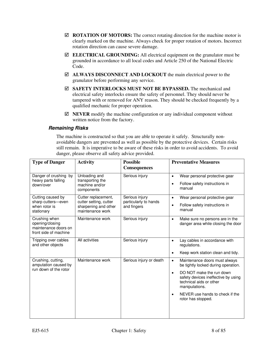
Remaining Risks

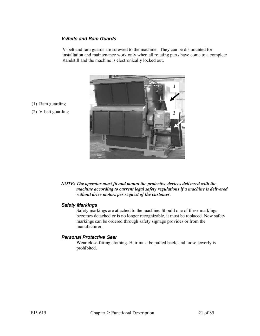
The machine is constructed so that you are able to operate it safely. Structurally non- avoidable dangers are prevented as well as possible by the protective devices. Certain risks still remain. It is imperative to be aware of these risks in order to avoid accidents. To avoid danger, please observe all safety advice provided.

Type of Danger

Activity

Possible

Preventative Measures


Consequences


Danger of crushing by

Unloading and

Serious injury

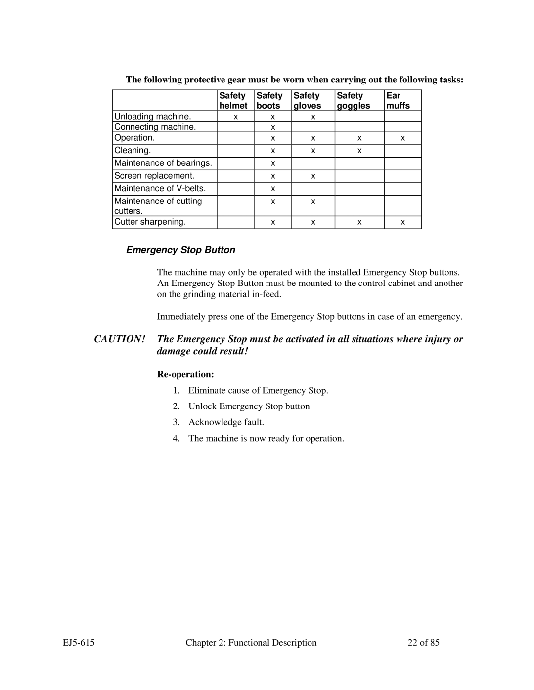
Wear personal protective gear

heavy parts falling

transporting the


Follow safety instructions in

down/over

machine and/or


manual


components


Cutting caused by

Cutter replacement,

Serious injury

Wear personal protective gear

sharp cutters—even

cutter setting, cutter

particularly to hands

Follow safety instructions in

when rotor is

sharpening and other

and fingers

manual

stationary

maintenance work


Crushing when

Maintenance work

Serious injury

Make sure no persons are in the

opening/closing


danger area while closing the door

maintenance doors on


front side of machine


Tripping over cables

All activities

Serious injury

Lay cables in accordance with

and other objects


regulations.


Keep work station clean and tidy.


Crushing, cutting,

Maintenance work

Serious injury or death

Maintenance doors must always

amputation caused by


be tightly locked during operation.

run down of the rotor


DO NOT make the run down


safety devices ineffective by using


technical aids or other


manipulations.


NEVER use hands to check if the


rotor has stopped.


EJ5-615

Chapter 1: Safety

8 of 85

Image 8
Contents SMS Medium Duty Single Shaft Shredder Shipping Info Storage, Disposal, Transportation StorageDisposal TransportationTable of Contents Safety Symbols Used in this Manual SafetyHow to Use This Manual General Safety Regulations ResponsibilityPage Remaining Risks EJ5-615 Safety Page Functional Description Models Covered in This ManualGeneral Description Mechanical SectionMaterial In-feed Typical Features and ComponentsMachine Standard Execution In-feed Hopper Additional In-feed DeviceRotor, cutters, bed cutters DriveRotor, Cutters, Bed Cutters Rotor cutter Screen support hydraulic Bed cutter Screen and screen support Discharge of Shredding Material Hydraulic Ram Pulse Push Function Protective Devices Safety FeaturesSafety Device for Housing Flap Personal Protective Gear Safety MarkingsBelts and Ram Guards Emergency Stop Button Re-operationInstallation Unloading and Installing the MachineUncrating the Equipment Requirements at Application SiteElectrical Connections Connection of Emergency Stop Button General Advice Initial Start-upChecking the Rotational Direction Machine Check Prior to Start-upPage Start-up Operation ProceduresOperation Emptying the Screen standard screen Emptying the Screen hydraulic screen Switch OFF Machine Shut-downMaintenance Plan MaintenancePreventative Maintenance Schedule Checking the Protective Devices Preventative and Corrective MaintenanceCleaning the Machine Replacing the Gear Box Replacing the RotorDismounting the Rotor Mounting the RotorMounting the Main Bearings Replacing the Main BearingsDismounting the Main Bearings Lubricating the Main Bearings Lubrication IntervalsShift Operation Replace Lubricant Check Check lubricant qualityReplacing Lubricant Replacing or Refilling LubricantRefilling lubricant BJ5-615 Maintenance Mounting and Dismounting TAPER-LOCK Tensioning Element Tightening Torque of the Screws Replacing the ScreenStandard Screen and Hydraulic Screen BeltsChecking the tension force of the V-belt Roller centres and 16mm sagProfile section Efficiency of x Newton Lbs Re-tensioning and relaxing the V-beltReplacing and Checking the Cutting Cutter Mountings Checking V-belt condition, replacing V-beltWorking on the Cutting Cutters Dismounting the Cutters see drawing below Torque Grade Screw typeChecking the Condition of the Cutters Dismounting the Cutter Holders Dismounting the Bed Cutters Mounting the Cutter Holders Make sure that the cutter holder fits properlyAdjust the gap between cutter and bed knife to 0.8-1.0 mm Mounting the CuttersMake sure the cutter fits planar in the seat Mounting the Bed CuttersSharpening Cutters and Bed Knives Setting the Cutting Knives Hydraulic Maintenance Transporting and Storing the Cutting CuttersFigure Checking and adjusting the hydraulic system Hydraulic liquid recommendation Troubleshooting IntroductionProblem Possible Cause Possible Remedy DepartmentMaterial Unsuitable screen Perforation Reduce feed quantity Warranty Returns AppendixReturned Material Policy Credit ReturnsTechnical Specifications Drawings and Diagrams Cutter MountingBed Knife Mounting Rotor Assembly Drive Ram Ram scraper SMS 850 Hydraulic Diagram SMS 850 Hydraulic Unit SMS 850 Hydraulic Screen Diagram SMS 850 Hydraulic Unit-Screen SMS 1200-2000 Standard Hydraulic Diagram SMS 1200-2000 Hydraulic Unit SMS 1200-2000 Hydraulic Screen Diagram SMS 1200-2000 Hydraulic Unit Spare Parts List SMSKnife rotor ø387x850 Hydraulic Knife rotor ø457x1130 Ram complete 107 Safety grid back 108 109 Ram residual chute 200 Knife rotor ø457x1410 SMS Knife rotor ø457x1950 SMS 850 Hydraulic Unit Spare Parts Pos Description Standard SupplierSMS 1200-2000 Hydraulic Screen Spare Parts SMS 850 Hydraulic Screen Spare PartsSMS 1200-2000 Hydraulic Unit Spare Parts Service Department Technical AssistanceParts Department Sales DepartmentSterling, Inc Th Street New Berlin, WI

1500, SMS 850, 2000, 1200 specifications

The Sterling 1200 and 2000, along with the SMS 850 and 1500, represent a leap forward in the technology and features available in modern industrial equipment.

The Sterling 1200 is designed with efficiency in mind. It boasts an advanced control system that allows for precise monitoring and adjustments, ensuring optimal performance. With a powerful engine and robust construction, the Sterling 1200 is built to withstand demanding conditions, making it suitable for various applications ranging from manufacturing to construction.

The Sterling 2000 takes things a step further, offering enhanced capacity and capabilities. It incorporates state-of-the-art technology, including automated diagnostics and predictive maintenance features. This not only minimizes downtime but also extends the lifespan of the equipment. The user-friendly interface allows operators to easily navigate and control various functions, ensuring smooth operations.

On the other hand, the SMS 850 is engineered for versatility. Its modular design allows for seamless integration with existing systems, providing flexibility in how it is used. The SMS 850 is equipped with the latest energy-efficient technologies, helping businesses reduce operational costs while maintaining high productivity levels. The compact size of the SMS 850 makes it ideal for facilities where space is at a premium, without compromising on power or performance.

The SMS 1500, a larger counterpart to the SMS 850, is designed for high-demand environments. It features advanced safety protocols, ensuring that operators can work with peace of mind. The SMS 1500 is capable of handling larger workloads, making it a preferred choice for larger industrial operations. Its real-time monitoring system provides valuable insights into performance metrics, enabling better decision-making and operational strategies.

Both the Sterling and SMS series prioritize advanced connectivity, allowing for integration with IoT platforms. This capability facilitates remote monitoring and control, enhancing operational efficiency. Overall, the Sterling 1200, 2000, SMS 850, and 1500 epitomize innovation in design and technology, helping businesses streamline their processes and stay competitive in the fast-paced industrial landscape. As industries continue to evolve, these models will play a crucial role in meeting the demands of tomorrow.