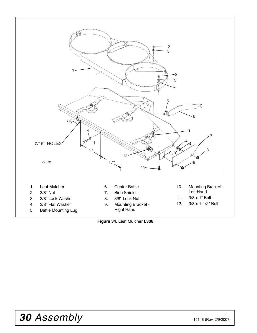
Woods Equipment L59A-3, L306A-3 manual Drive Pulley Installation, Manual Lift Installation

Page 22

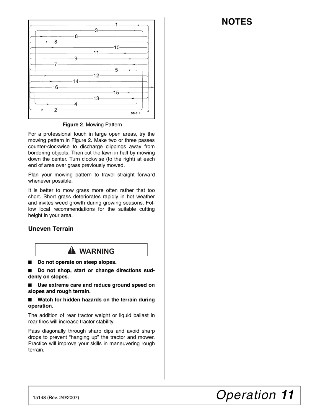
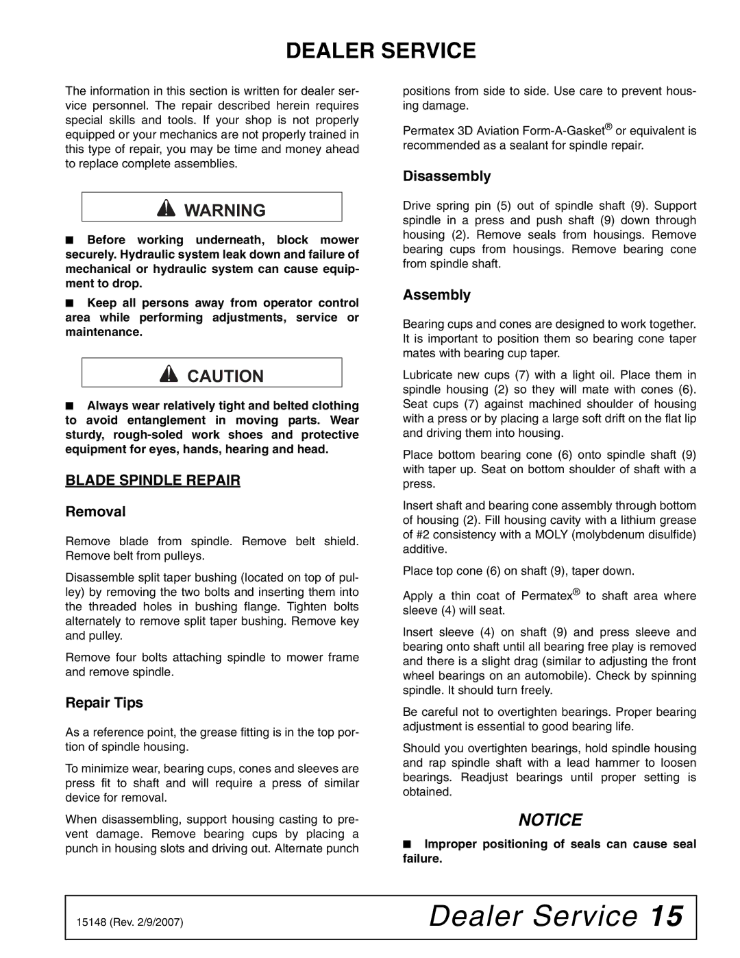
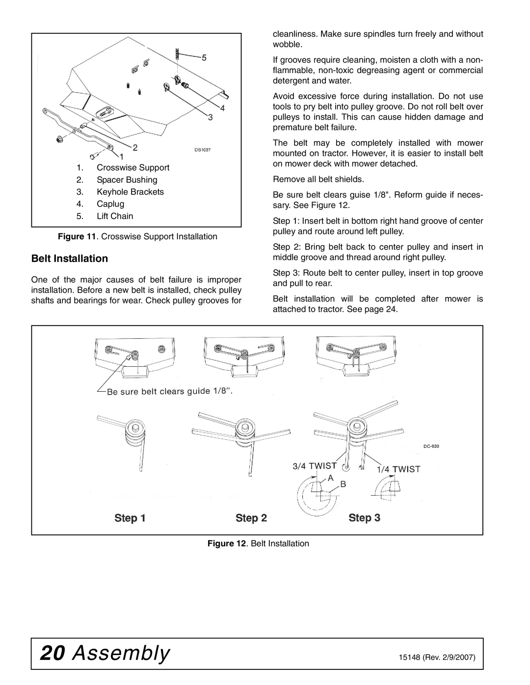
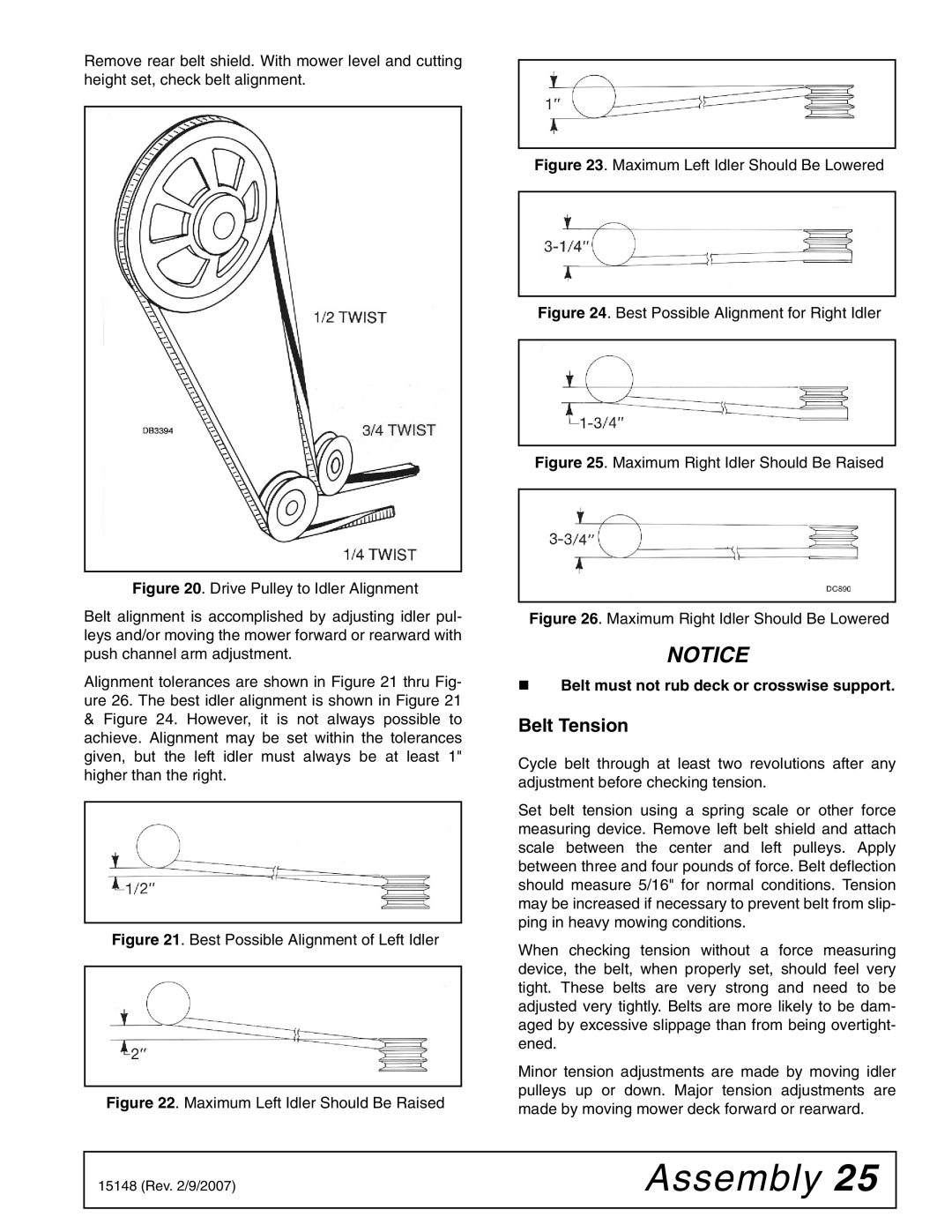
1.Idler Pulley

2.Rear Belt Guide

3.Idler Bracket

4.5/8 x 2-1/2" Carriage Bolt

5.5/8" Flat Washer

6.5/8" Lock Washer

7.5/8" Hex Nut

Figure 15. Idler Pulley Installation

Drive Pulley Installation

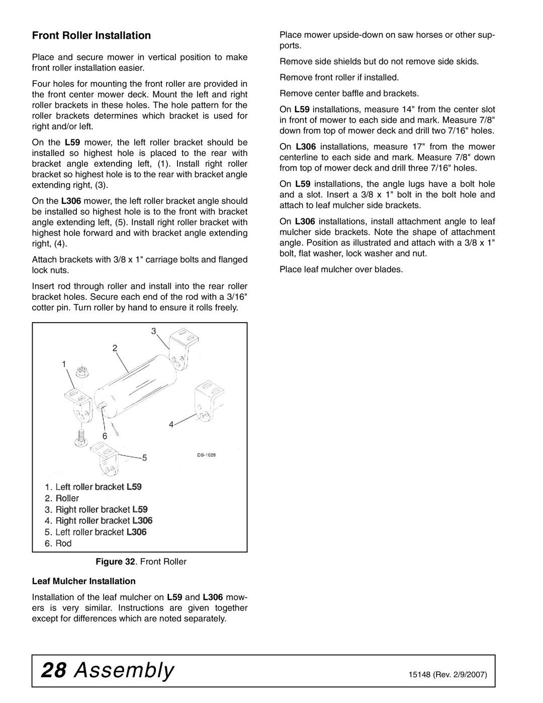
A split taper splined bushing is used to locate and secure drive pulley to belt pulley shaft. This provides an easy on-off feature.

To remove bushing, remove bolts securing it to pulley and shaft and place them into threaded bushing holes. Tighten evenly to press bushing out of pulley.

Clean paint from center pulley hole and insert split taper bushing into hole. Insert bolts through unthreaded bushing holes and into threaded holes of drive pulley, but do not tighten.

Install drive pulley over belt pulley shaft as far as possi- ble.

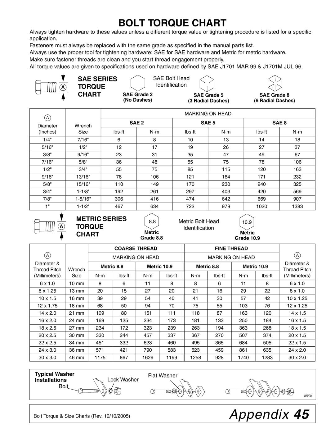
Alternately tighten the splined bushing bolts to secure the drive pulley. Continue to alternate the tightening sequence until assembly is tight and all bolts are torqued to 12 ft-lbs.

NOTICE

Be sure to torque bolts to exactly 12 lbs-ft. Do not overtighten or pulley casting may crack.

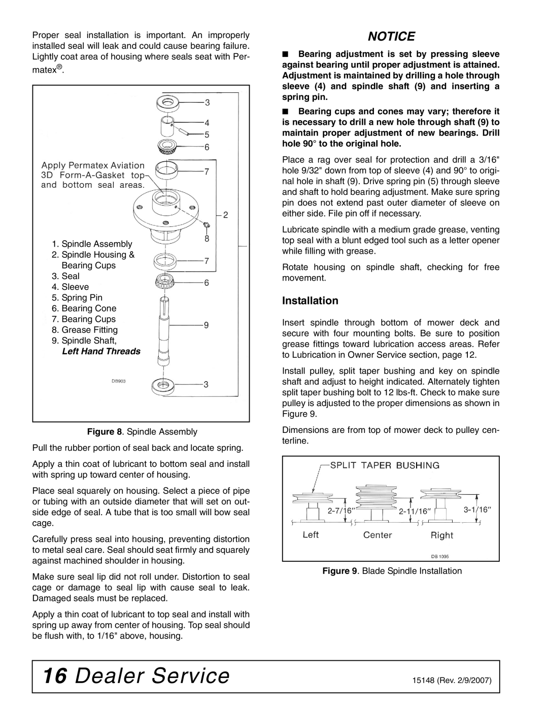
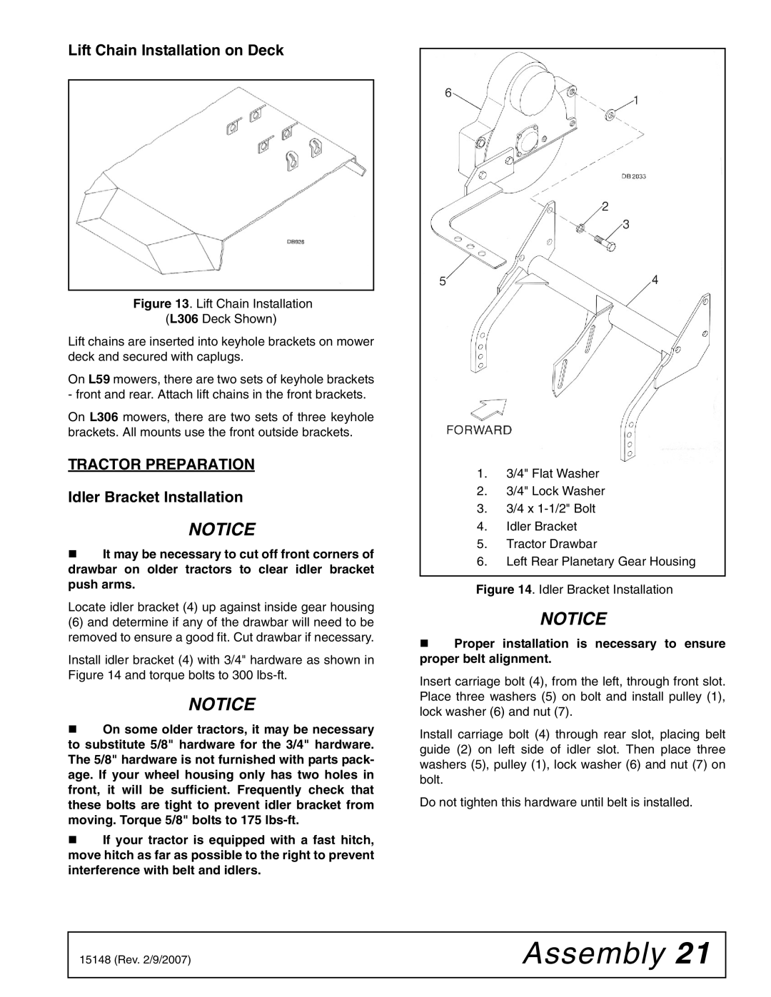
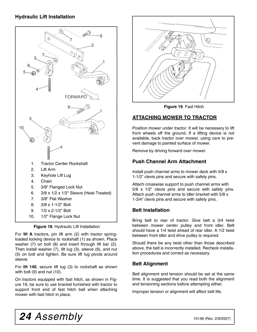
Install belt shield bracket (5) to PTO housing as shown in Figure 16 with bolt (10) and lock washer (11). Install belt shield bracket (3) to tractor bracket as shown with bolt (10), lock washer (11), and nut (12).

Do not install belt shield until belt has been installed. Shield will bolt to brackets (3 & 5).

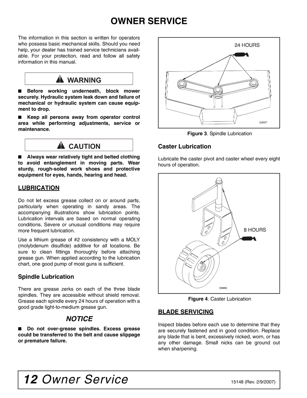
1.Drive Pulley

2.Belt

3.Belt Shield Bracket

4.Belt Shield

5.Belt Shield Bracket

10.3/8 x 1" Bolt

11.3/8" Lock Washer

12.3/8" Nut

Figure 16. Drive Pulley Installation

Manual Lift Installation

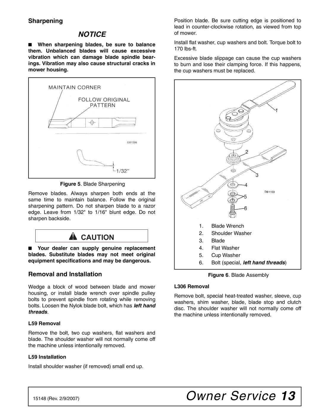
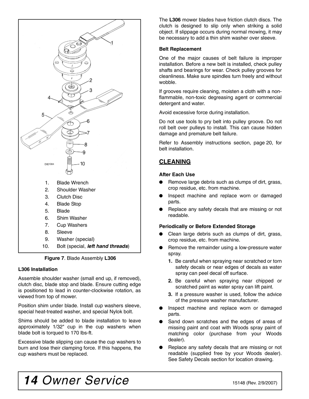
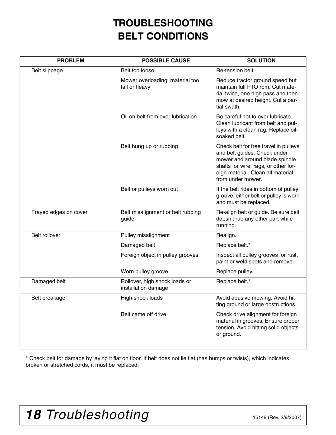
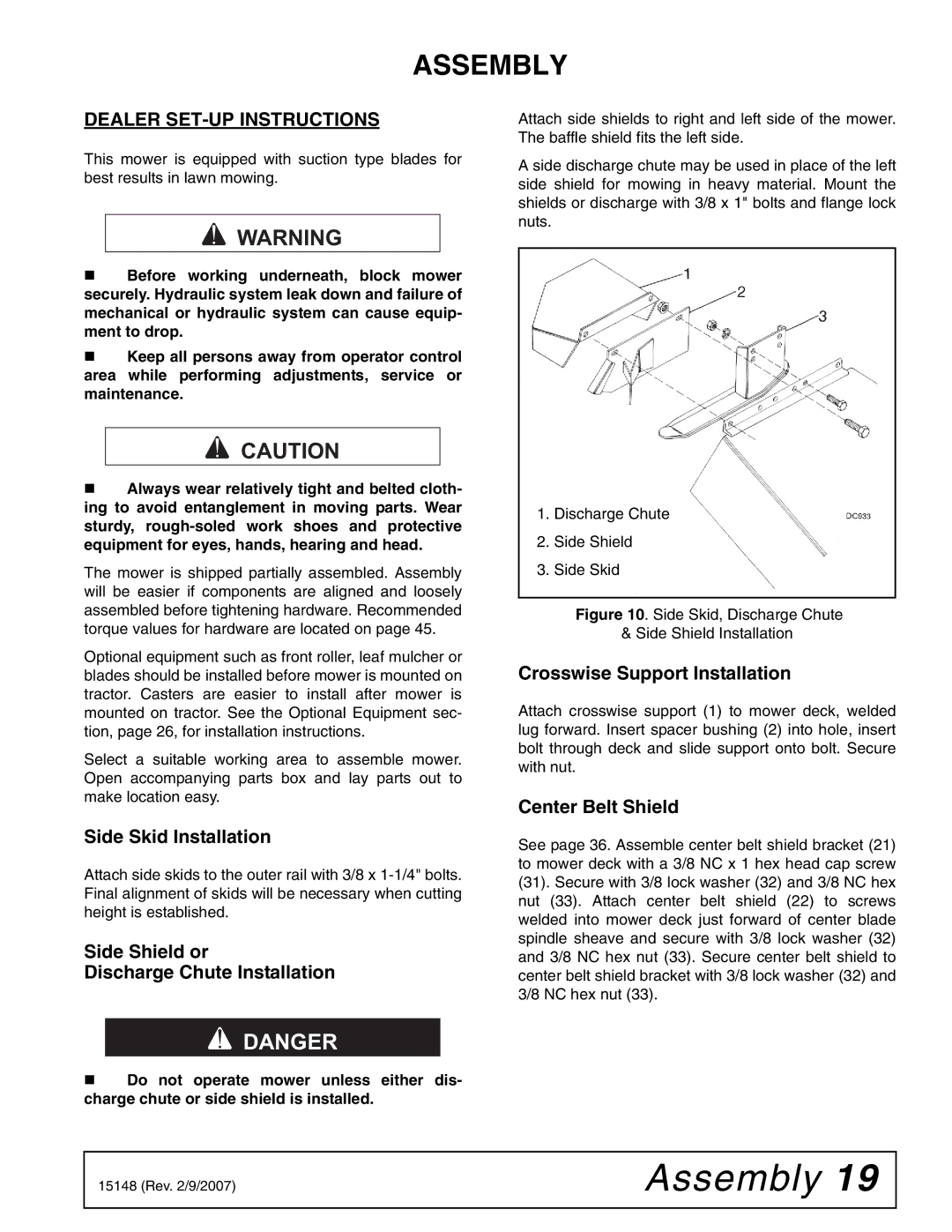
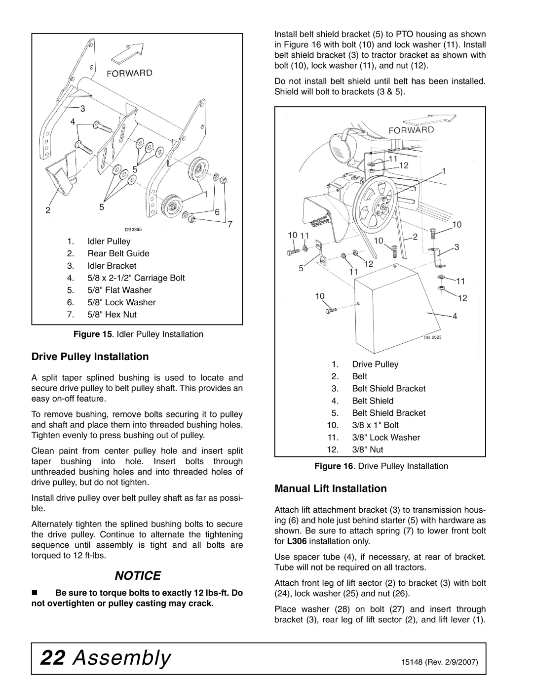
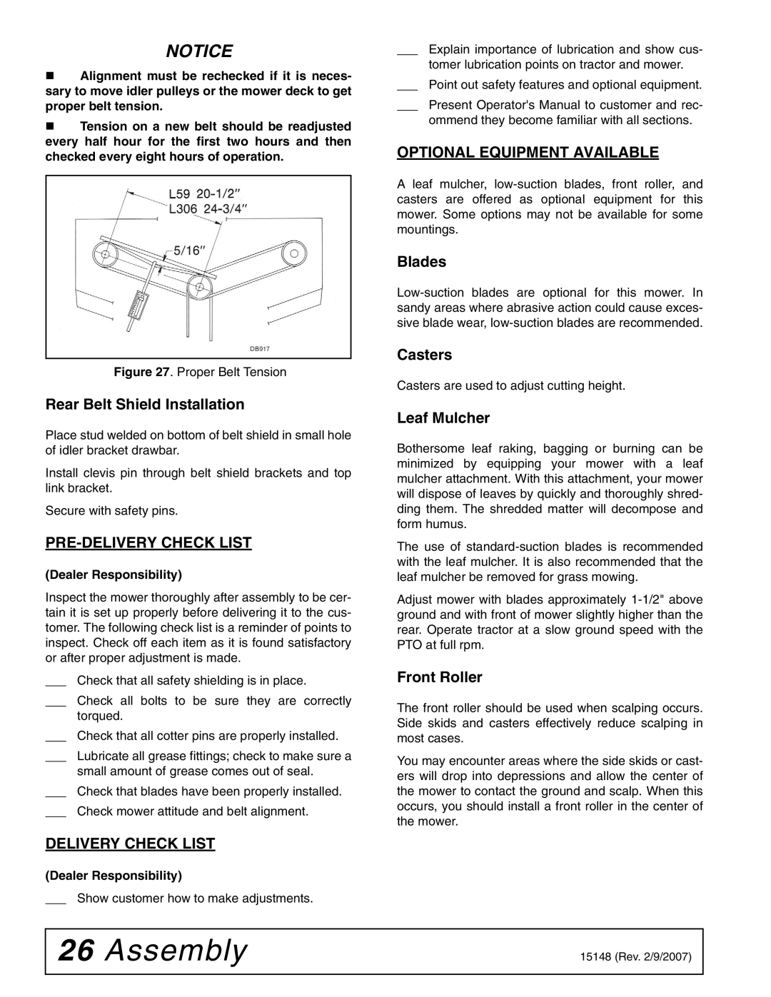
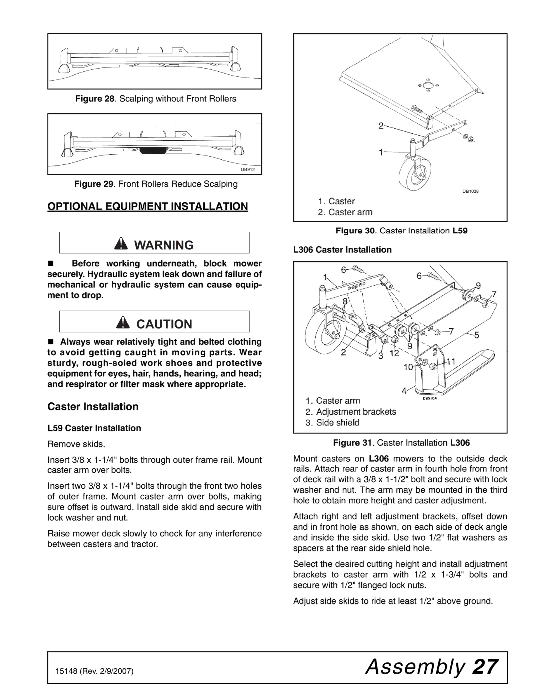
Attach lift attachment bracket (3) to transmission hous- ing (6) and hole just behind starter (5) with hardware as shown. Be sure to attach spring (7) to lower front bolt for L306 installation only.

Use spacer tube (4), if necessary, at rear of bracket. Tube will not be required on all tractors.

Attach front leg of lift sector (2) to bracket (3) with bolt (24), lock washer (25) and nut (26).

Place washer (28) on bolt (27) and insert through bracket (3), rear leg of lift sector (2), and lift lever (1).

22 Assembly

15148 (Rev. 2/9/2007)


Image 22
Contents Rotary Mower Introduction To the DealerTable of Contents LEA EL InstructivoGeneral Information SpecificationsL59A-3 L306A-3 Training SafetySafety Rules PreparationTransportation MaintenanceStorage Safety & Instructional Decals Serial Number PlateOperation AdjustmentsCutting Height Adjustment OperationStarting and Stopping Mower Side Skid AdjustmentMower Attitude PRE-OPERATION Check ListMowing Techniques TransportingCommencing Mowing Mowing SpeedUneven Terrain Lubrication Owner ServiceOwner Service Blade ServicingSharpening Removal and InstallationL59 Installation L59 RemovalBelt Replacement CleaningL306 Installation After Each UseDealer Service Dealer ServiceBlade Spindle Repair Installation Left Hand ThreadsTroubleshooting Troubleshooting Mowing ConditionsTroubleshooting Belt Conditions Assembly AssemblyDealer SET-UP Instructions Belt Installation Crosswise Support InstallationIdler Bracket Installation Lift Chain Installation on DeckTractor Preparation Drive Pulley Installation Manual Lift InstallationManual Lift Installation Push Channel Arm Attachment Hydraulic Lift InstallationAttaching Mower to Tractor Belt AlignmentBelt Tension Belt must not rub deck or crosswise supportDelivery Check List PRE-DELIVERY Check ListOptional Equipment Available L59 Caster Installation Optional Equipment InstallationCaster Installation L306 Caster InstallationFront Roller Installation Leaf Mulcher InstallationAssembly Leaf Mulcher L306 Parts Index PartsL59 A-3 Frame Assembly Part QTY Description L306 A-3 Frame Assembly 3885 16 x 3/16 x 1-1/4 Key Rev /9/2007 L59 A-3 & L306 A-3 Mounting Assembly Part QTY Description Hardware L59 A-3 & L306 A-3 Manual Height Adjustment Assembly L59 A-3 Blade Assembly L306 A-3 Blade AssemblyL59 A-3 & L306 A-3 Blade Spindle Assembly L59 A-3 & L306 A-3 Front Roller Assembly OptionalL59 A-3 Caster Assembly Optional L306 A-3 Caster Assembly Optional L59 A-3 Leaf Mulcher Assembly Optional L306 A-3 Leaf Mulcher Assembly Optional Appendix Bolt Torque ChartSAE Series Torque Chart Metric SeriesBolt Size Chart AbbreviationsAssembly IndexWarranty Rev /23/2005 15148 Woods Equipment Company