3Com Switch 8800 Family
United States Government Legend
3Com Corporation Campus Drive Marlborough, MA USA
Contents
Examining Installation Site Installation Tools
Switch Installation
Protocols that are used to interconnect LANs
Conventions
Lists icon conventions that are used throughout this guide
Lists text conventions that are used throughout this guide
Related
Switch
Documentation
About this Document
8800s
Preface
3Com Switch 8810 10-Slot Chassis
3Com Switch 8814 14-Slot Chassis
Switch 8807 slots
Chassis and Slots Switch
Switch 8810 slots
Structure
Switch
Functions
Each Ethernet port can deliver up to 15.4 W to its PD
AC Power System
Specifications Switch
PoE entry area
External PoE Power Rack 3C17509
Label Color State Abnormal reason
Mbus Introduction
Normal Abnormal
Role and function
Fan tray panel of the Switch 8800 Family
Panel
Gbps Switch Fabric
Fabric Modules
Compact Flash CF slot
RS232/485 port specifications
Management Ports
Status LEDs for the management 10Base-T/100Base-TX port
Console port specifications
Reset button
AUX port specifications
Status LEDs
Gbps Switch Fabric LED Status
Status LEDs for the 360 Gbps Switch Fabric module
CF status LED
Status LEDs for I/O module
720 Gbps Switch Fabric specifications
Gbps Switch Fabric Technical specifications
AUX port
Status LEDs for the 720 Gbps Switch Fabric module
Technical specifications of the Switch 8800 Family
Status LEDs for the 720 Gbps Switch Fabric module
Software features of the Switch 8800 Family
Software Features
Supported software features
Lacp
Software features of the Switch 8800 Family
Product Overview
3C17511 module specifications
O modules available to the Switch 8800 Family
Overview
3C17511 1-port 10GBASE-X Xenpak
3C17512 2-port 10GBASE-X XFP Module
3C17512 module specifications
Panel and LEDs 3C17511 module panel
Port LEDs on the 3C17511 module
Panel and LEDs Figure
Specifications
3C17513 12-port 1000BASE-X SFP Module
3C17513 module has two LEDs for each port on its panel
3C17514 24-port 1000BASE-X SFP Module
10/100/1000BASE-T
3C17516 24-port
Module
3C17525 1-port 10GBASE-X Advanced Xenpak Module
3C17526 4-port 10GBASE-X XFP Module
3C17526 module specifications
Panel and LEDs 3C17525 module panel
Port LEDs on the 3C17525 module
3C17527 2-port 10GBASE-X XFP Advanced Module
3C17527 module specifications
3C17526 module panel
1000 Mbps optical port LEDs on the 3C17526 module
3C17528 module has one LED for each port on its panel
3C17528 48port 10/100/1000 BASE-T RJ-45 Module
Panel and LEDs 3C17530 module panel
3C17530 24-port 1000BASE-X SFP Advanced Module
3C17531 24-port 10/100/1000BASE-T Advanced Module
3C17531 module has one LED for each port on its panel
3C17532 module specifications
Panel and LEDs 3C17531 module panel
Port LEDs on the 3C17531 module
Panel and LEDs 3C17533 module panel
3C17533 24-port 1000BASE-X SFP IPv6 Module
3C17532 module has one LED for each port on their panel
3C17536 module specifications
3C17534 module specifications
3C17534 24-port 10/100/1000BASE-T IPv6 Module
3C17536 4-port 10GBASE-X XFP Quad IPv6 Module
3C17537 2-port 10GBASE-X XFP IPv6 Module
3C17537 module specifications
Panel and LEDs 3C17536 module panel
1000 Mbps optical port LEDs on the 3C17536 module
3C17538 48-port 1000BASE-X SFP IPv6 Module
3C17538 module specifications
Panel and LEDs 3C17537 module panel
1000 Mbps optical port LEDs on the 3C17537 module
Front panel
Technical specifications for the 3C17542
Technical specifications for the 3CR1754766
Technical specifications for the 3C17546
Available cables
Status LEDs on the 3C17546
Status LEDs on the 3CR1754766
Technical specifications for the 3C17548
Transceivers
Documents the 3Com Switch 8800 Family transceivers
Transceiver Specifications
Densities
Switch 8800 Port
Switch 8800 Available Modules
O and Application Modules
General Safety
Safety
Recommendations
Recommendations
Installation Preparation
Mechanical active material Unit Content
Limitation on dust content in equipment room
Harmful gas limits in an equipment room
Gas Average mg/m3 Max. mg/m3
Power Supply Requirements Space Requirements
Installation Tools
Required installation tools
Measure
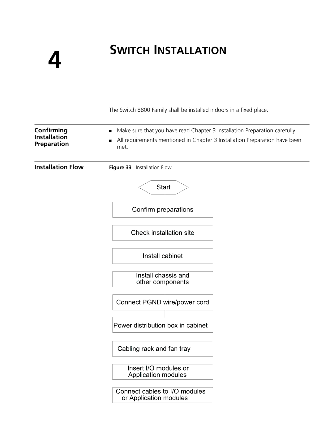
Installation Flow
Confirming Installation Preparation
One Switch 8807 chassis in a cabinet
Mounting the Switch User-Supplied Cabinet
One Switch 8807 chassis in a cabinet Switch 8807 11U
Two Switch 8807 chassis in a cabinet
Two Switch 8807 chassis in a cabinet Switch 8807 11U
One Switch 8810 chassis in a cabinet
One Switch 8810 chassis in a cabinet Switch 8810 14U
One Switch 8814 chassis in a cabinet
Cabinet
One Switch 8814 chassis in a cabinet Switch 8814 17U
Other grounding environment
Connecting Pgnd Wire and Power Cord
Connecting Pgnd Wire Common grounding environment
Ground the switch when ground bar is available
Ground the switch via AC PE wire
Connecting AC Power Cord
Connect AC power cord to the Switch
Grounding PoE chassis
Connecting PoE power cable
Fan tray is hot swappable
Installing Fan Tray
Install mounting ears onto the both sides of the switch
Contact take the fan tray out from the packing bag
Lightning Protection Box
Fasten the screw on top of the PoE lightning protection box
Installing I/O modules
Connecting console cable
Connecting Interface Cables
RJ-45 Signal Direction DB-25 DB-9
Introduction
AUX cable pinouts
AUX cable
Introduction to RJ-45 connector
Connecting AUX cable
Connecting category-5 shielded cable
Connecting Fiber
Intertwinement or bending is allowed
Cable Routing Recommendations
Cable Management
Cable bundling example
Cable fixing example
Installation checking list
Verifying Installation
Tie-binding parameters
Cable bundle diameter mm Space between bundles mm
Switch Installation
Configuration
Setting up
Connecting the Cables
Environment
Verifying Installation Before Powering Switch
Powering and Booting the Switch
Zbbtest
Debugging the System
LEDs on the PSU
Troubleshooting the PSU
Indicator State description
Display Power Command Indicates the PSU is Not in Position
Input LED green and Output LED green are OFF
Fail LED red is on Check that
Indicator
Hardware Maintenance
Replacing AC PSU
Removing an AC PSU
Removing and cleaning the air filter of PSU
Installing an AC PSU
Replacing and Cleaning Chassis’s Air Filter
Installing the air filter of PSU
Installing the Chassis’s Air Filter
Removing and Cleaning the Chassis’s Air Filter
Required tools
Removing a Module
Replacing the Fan Tray
Installing a Module
Replacing the Fan Tray Required tools
Required cables
Upgrading
Software
Main Menu
Serial Submenu
Please Select File Xmodem downloading ...CCC
This procedure uses a Switch 8814 work as the Tftp client
Tftp and to 0x0 if you are using FTP
This procedure uses a Switch 8814 work as the FTP client
Using FTP Port using FTP
Load host program
Using FTP
Using Tftp
Boot ROM and host program loading process is now complete
Configuration did not save during the I/O module reboot
Program
Representative
Password Loss
Insufficient Flash memory
Switch Monitoring and Maintenance
Lightning Arrester
Power
Use the nylon ties to bundle the cables neatly
Installing a Lightning Arrester for Network Port
Installation procedure
Installation diagram of a network port’s lightning arrester
Installation precautions
Chapter a Lightning Protection of the Switch
Supervisor
3Com Network
Director
Access Manager
Network Node
HP OpenView
Manager
Application such as 3Com Enterprise Management Suite EMS
Appendix B 3COM Network Management