3M™ | 23 |
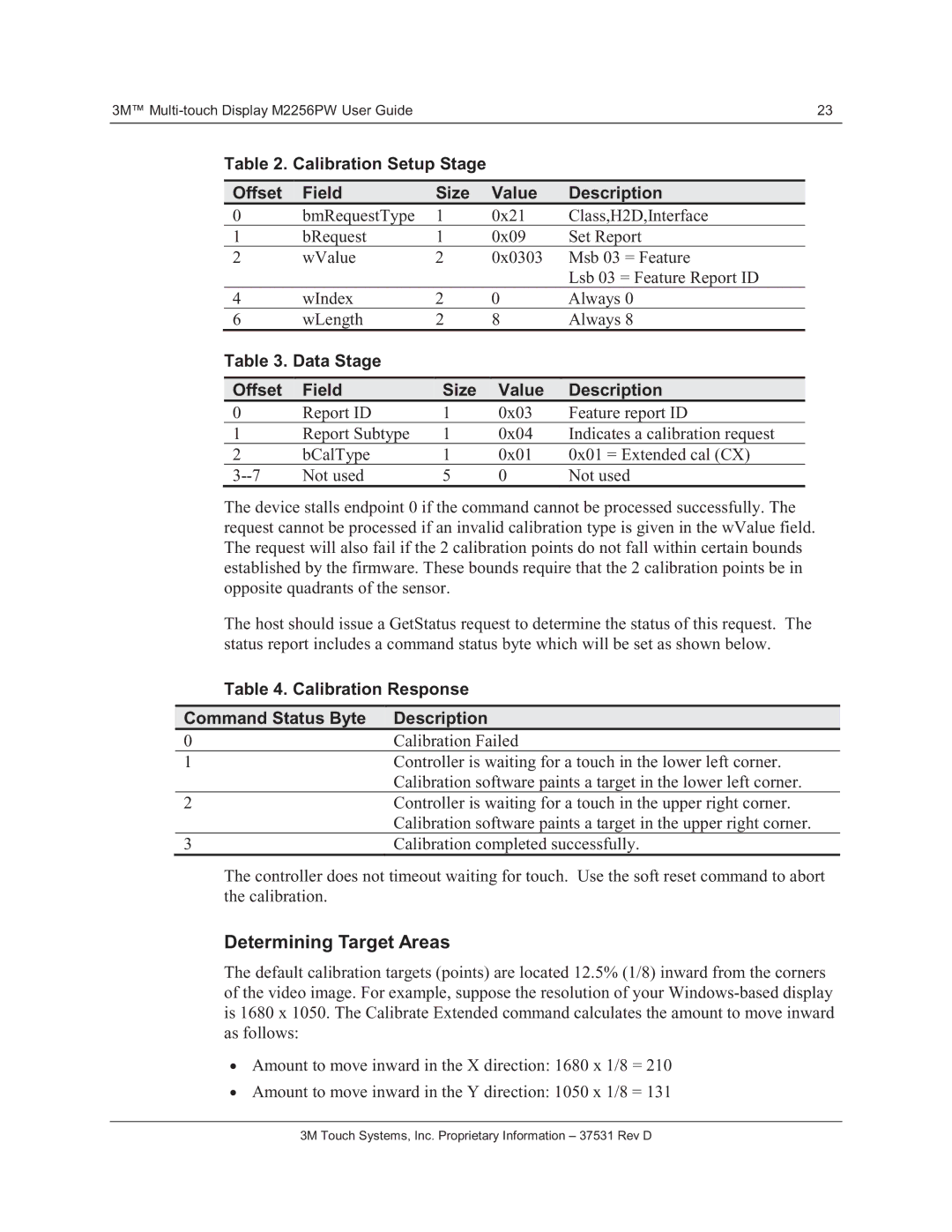
Table 2. Calibration Setup Stage
Offset | Field |
| Size | Value | Description |
| |||||
0 | bmRequestType | 1 | 0x21 | Class,H2D,Interface | |
1 | bRequest | 1 | 0x09 | Set Report | |
2 | wValue | 2 | 0x0303 | Msb 03 = Feature | |
|
|
|
|
| Lsb 03 = Feature Report ID |
4 | wIndex | 2 | 0 | Always 0 | |
6 | wLength | 2 | 8 | Always 8 | |
Table 3. Data Stage |
|
|
|
| |
|
|
|
|
|
|
Offset | Field |
| Size | Value | Description |
0 | Report ID | 1 | 0x03 | Feature report ID | |
1 | Report Subtype | 1 | 0x04 | Indicates a calibration request | |
2 | bCalType | 1 | 0x01 | 0x01 = Extended cal (CX) | |
Not used | 5 | 0 | Not used | ||
The device stalls endpoint 0 if the command cannot be processed successfully. The request cannot be processed if an invalid calibration type is given in the wValue field. The request will also fail if the 2 calibration points do not fall within certain bounds established by the firmware. These bounds require that the 2 calibration points be in opposite quadrants of the sensor.
The host should issue a GetStatus request to determine the status of this request. The status report includes a command status byte which will be set as shown below.
Table 4. Calibration Response
Command Status Byte | Description |
0 | Calibration Failed |
1 | Controller is waiting for a touch in the lower left corner. |
| Calibration software paints a target in the lower left corner. |
2 | Controller is waiting for a touch in the upper right corner. |
| Calibration software paints a target in the upper right corner. |
3 | Calibration completed successfully. |
The controller does not timeout waiting for touch. Use the soft reset command to abort the calibration.
Determining Target Areas
The default calibration targets (points) are located 12.5% (1/8) inward from the corners of the video image. For example, suppose the resolution of your
•Amount to move inward in the X direction: 1680 x 1/8 = 210
•Amount to move inward in the Y direction: 1050 x 1/8 = 131