3M™ | 35 |
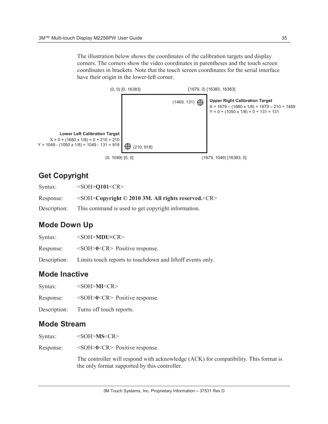
The illustration below shows the coordinates of the calibration targets and display corners. The corners show the video coordinates in parentheses and the touch screen coordinates in brackets. Note that the touch screen coordinates for the serial interface have their origin in the
(0, 0) [0, 16383] | (1679, 0) [16383, 16383] | ||||
|
|
|
|
| Upper Right Calibration Target |
|
| (1469, 131) |
|
| |
|
|
|
| ||
|
|
|
| X = 1679 – (1680 x 1/8) = 1679 – 210 = 1469 | |
|
|
|
|
| |
|
|
|
|
| |
|
|
|
|
| Y = 0 + (1050 x 1/8) = 0 + 131 = 131 |
Lower Left Calibration Target |
|
| |
X = 0 + (1680 x 1/8) = 0 + 210 | = 210 |
|
|
Y = 1049 - (1050 x 1/8) = 1049 - 131 | = 918 |
| (210, 918) |
|
|
| |
(0, 1049) [0, 0] | (1679, 1049) [16383, 0] |
Get Copyright
Syntax: | <SOH>Q101<CR> |
Response: | <SOH>Copyright © 2010 3M. All rights reserved.<CR> |
Description: | This command is used to get copyright information. |
Mode Down Up
Syntax: | <SOH>MDU<CR> |
Response: | <SOH>0<CR> Positive response. |
Description: | Limits touch reports to touchdown and liftoff events only. |
Mode Inactive
Syntax: <SOH>MI<CR>
Response: | <SOH>0<CR> Positive response. |
Description: Turns off touch reports.
Mode Stream
Syntax: | <SOH>MS<CR> |
Response: | <SOH>0<CR> Positive response. |
| The controller will respond with acknowledge (ACK) for compatibility. This format is |
| the only format supported by this controller. |
