GAS CONNECTIONS
![]() WARNING
WARNING
THIS BOILER IS NOT INTENDED TO OPERATE AT GAS SUPPLY PRESSURE OTHER THAN SHOWN ON THE RATING PLATE. EXPOSURE TO HIGHER GAS SUPPLY PRESSURE MAY CAUSE DAMAGE TO GAS VALVES WHICH CAN RESULT IN FIRE OR EXPLOSION. IF OVERPRESSURE HAS OCCURRED SUCH AS THROUGH IMPROPER TESTING OF GAS LINES OR EMERGENCY MALFUNCTION OF THE SUPPLY SYSTEM, THE GAS VALVES MUST BE CHECKED FOR SAFE OPERATION. MAKE SURE THAT THE OUTSIDE VENTS ON THE SUPPLY REGULATORS AND THE SAFETY VENT VALVES ARE PROTECTED AGAINST BLOCKAGE. THESE ARE PARTS OF THE GAS SUPPLY SYSTEM, NOT THE BOILER. VENT BLOCKAGE MAY OCCUR DURING ICE
WHEN LOCAL CODES REQUIRE A MAIN MANUAL
threads of pipe joints. Do not apply compound to the first two threads. Use compounds resistant to the action of liquefied petroleum gases.
THE BOILER MUST BE ISOLATED FROM THE GAS SUPPLY PIPING SYSTEM BY CLOSING ITS MAIN MANUAL GAS
1.CORRECT GAS - Make sure gas on which the boiler will operate is the same as that specified on the rating plate. Do not install the boiler if equipped with a different type of gas. Consult your gas supplier.
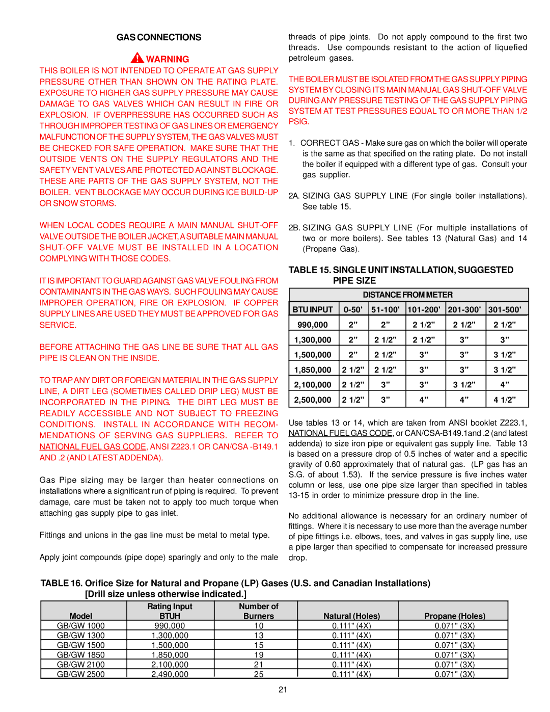
2A. SIZING GAS SUPPLY LINE (For single boiler installations). See table 15.
2B. SIZING GAS SUPPLY LINE (For multiple installations of two or more boilers). See tables 13 (Natural Gas) and 14 (Propane Gas).
IT IS IMPORTANT TO GUARDAGAINST GAS VALVE FOULING FROM CONTAMINANTS IN THE GAS WAYS. SUCH FOULING MAY CAUSE IMPROPER OPERATION, FIRE OR EXPLOSION. IF COPPER SUPPLY LINES ARE USED THEY MUST BE APPROVED FOR GAS SERVICE.
BEFORE ATTACHING THE GAS LINE BE SURE THAT ALL GAS PIPE IS CLEAN ON THE INSIDE.
TO TRAP ANY DIRT OR FOREIGN MATERIAL IN THE GAS SUPPLY LINE, A DIRT LEG (SOMETIMES CALLED DRIP LEG) MUST BE INCORPORATED IN THE PIPING. THE DIRT LEG MUST BE READILY ACCESSIBLE AND NOT SUBJECT TO FREEZING CONDITIONS. INSTALL IN ACCORDANCE WITH RECOM- MENDATIONS OF SERVING GAS SUPPLIERS. REFER TO NATIONAL FUEL GAS CODE, ANSI Z223.1 OR CAN/CSA
Gas Pipe sizing may be larger than heater connections on installations where a significant run of piping is required. To prevent damage, care must be taken not to apply too much torque when attaching gas supply pipe to gas inlet.
Fittings and unions in the gas line must be metal to metal type.
Apply joint compounds (pipe dope) sparingly and only to the male
TABLE 15. SINGLE UNIT INSTALLATION, SUGGESTED PIPE SIZE
DISTANCE FROM METER
BTU INPUT |
| |||||
990,000 | 2" | 2" | 2 1/2" | 2 1/2" | 2 1/2" |
|
1,300,000 | 2" | 2 1/2" | 2 1/2" | 3" | 3" |
|
1,500,000 | 2" | 2 1/2" | 3" | 3" | 3 1/2" |
|
1,850,000 | 2 1/2" | 2 1/2" | 3" | 3" | 3 1/2" |
|
2,100,000 | 2 1/2" | 3" | 3" | 3 1/2" | 4" |
|
2,500,000 | 2 1/2" | 3" | 4" | 4" | 4 1/2" |
|
|
|
|
|
|
|
|
Use tables 13 or 14, which are taken from ANSI booklet Z223.1, NATIONAL FUEL GAS CODE, or
No additional allowance is necessary for an ordinary number of fittings. Where it is necessary to use more than the average number of pipe fittings i.e. elbows, tees, and valves in gas supply line, use a pipe larger than specified to compensate for increased pressure drop.
TABLE 16. Orifice Size for Natural and Propane (LP) Gases (U.S. and Canadian Installations) [Drill size unless otherwise indicated.]
| Rating Input | Number of |
|
|
Model | BTUH | Burners | Natural (Holes) | Propane (Holes) |
GB/GW 1000 | 990,000 | 10 | 0.111" (4X) | 0.071" (3X) |
GB/GW 1300 | 1,300,000 | 13 | 0.111" (4X) | 0.071" (3X) |
GB/GW 1500 | 1,500,000 | 15 | 0.111" (4X) | 0.071" (3X) |
GB/GW 1850 | 1,850,000 | 19 | 0.111" (4X) | 0.071" (3X) |
GB/GW 2100 | 2,100,000 | 21 | 0.111" (4X) | 0.071" (3X) |
GB/GW 2500 | 2,490,000 | 25 | 0.111" (4X) | 0.071" (3X) |
21
