STANDARD (VERTICAL) VENTING, CATEGORY I
THIS BOILER MAY BE VENTED ACCORDING TO TABLE 7 (ALSO SEE FIGURE 5). AT LEAST TYPE B VENTING MUST BE USED WITH THE STANDARD VENTING OPTION
VENT SIZING, INSTALLATION AND TERMINATION SHALL BE IN ACCORDANCE WITH THE NATIONAL FUEL GAS CODE, ANSI Z223.1 OR
Vent connections must be made to an adequate stack or chimney and shall be in accordance with the National Fuel Gas Code, ANSI Z223.1 or
Horizontal runs of vent pipe shall be securely supported by adequately placed (approximately every 4 feet [1.2 m]), noncombustible hangers suitable for the weight and design of the materials employed to prevent sagging and to maintain a minimum upward slope of 1/4" per foot (2 cm/m) from the boiler to the vent terminals. Dampers or other obstructions must not be installed in the vent. Be sure that the vent connector does not extend beyond the inside wall of the chimney.
Table 11: VENT CONNECTION
VENT CONNECTOR | MODEL NUMBER |
G(W,B) 1000 | 10" (25.4 cm) |
G(W,B) 1300 | 12" (30.5 cm) |
G(W,B) 1500 | 12" (30.5 cm) |
G(W,B) 1850 | 14" (35.6 cm) |
G(W,B) 2100 | 14" (35.6 cm) |
G(W,B) 2500 | 16" (40.6 cm) |
|
|
For vent arrangements other than table 7 and for proper boiler operation, a barometric damper is required to maintain draft between
STANDARD (HORIZONTAL) VENTING, CATEGORY III
Vent sizing, installation and termination shall be in accordance with the NATIONAL FUEL GAS CODE, ANSI Z223.1 OR
For Category III installations, It is important that the Installed vent be airtight. Please insure that all joints are sealed properly during installation.
DIRECT VENT VERTICALAND HORIZONTAL VENTING
For direct vent applications this boiler may be vented according to tables 9 and 10. For category III applications, the exhaust vent pipe must be special gas vent pipe listed for use with category III gas burning heaters such as
When sizing exhaust piping and intake air piping,
The intake air piping can be PVC, CPVC, ABS or any suitable intake air piping that can be sealed.
Combustion air from outside the building ducted to boiler air inlet (Ducted Air Application) cannot be used in rooms with negative pressure.
HORIZONTAL VENT INSTALLATION
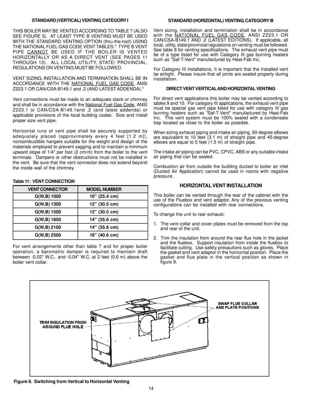
This boiler can be vented through the rear of the cabinet with the use of the Fluebox and vent adaptor. Any of the previous venting configurations can be installed with rear connections.
To change the unit to rear exhaust:
1.The vent collar and cover plates must be removed from the top and rear of the unit.
2.Trim the insulation from around the rear flue hole in the jacket and the fluebox. Support insulation from inside the fluebox to facilitate cutting. Use safety precautions such as gloves. Place the gasket and vent adaptor in the horizontal position. Place the gasket and flue plate in the vertical position as shown in figure 9.
Figure 9. Switching from Vertical to Horizontal Venting
14
