CONTROL SYSTEM
DESCRIPTION OF MULTI-STAGE FIRING SYSTEM
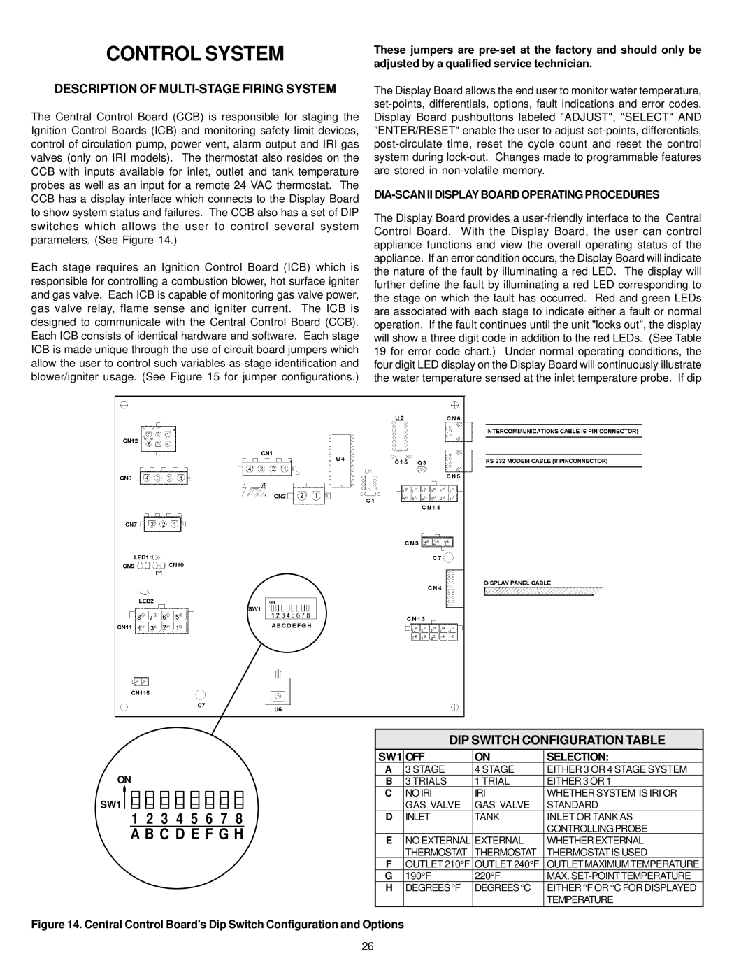
The Central Control Board (CCB) is responsible for staging the Ignition Control Boards (ICB) and monitoring safety limit devices, control of circulation pump, power vent, alarm output and IRI gas valves (only on IRI models). The thermostat also resides on the CCB with inputs available for inlet, outlet and tank temperature probes as well as an input for a remote 24 VAC thermostat. The CCB has a display interface which connects to the Display Board to show system status and failures. The CCB also has a set of DIP switches which allows the user to control several system parameters. (See Figure 14.)
Each stage requires an Ignition Control Board (ICB) which is responsible for controlling a combustion blower, hot surface igniter and gas valve. Each ICB is capable of monitoring gas valve power, gas valve relay, flame sense and igniter current. The ICB is designed to communicate with the Central Control Board (CCB). Each ICB consists of identical hardware and software. Each stage ICB is made unique through the use of circuit board jumpers which allow the user to control such variables as stage identification and blower/igniter usage. (See Figure 15 for jumper configurations.)
These jumpers are
The Display Board allows the end user to monitor water temperature,
DIA-SCAN II DISPLAY BOARD OPERATING PROCEDURES
The Display Board provides a
ON
SW1
1 2 3 4 5 6 7 8 A B C D E F G H
DIP SWITCH CONFIGURATION TABLE
SW1 OFF | ON | SELECTION: |
| |
A | 3 STAGE | 4 STAGE | EITHER 3 OR 4 STAGE SYSTEM |
|
B | 3 TRIALS | 1 TRIAL | EITHER 3 OR 1 |
|
C | NOIRI | IRI | WHETHER SYSTEM IS IRI OR |
|
| GAS VALVE | GAS VALVE | STANDARD |
|
D | INLET | TANK | INLET OR TANK AS |
|
|
|
| CONTROLLING PROBE |
|
E | NO EXTERNAL EXTERNAL | WHETHER EXTERNAL |
| |
| THERMOSTAT | THERMOSTAT | THERMOSTAT IS USED |
|
FOUTLET 210°F OUTLET 240°F OUTLETMAXIMUMTEMPERATURE
G | 190°F | 220°F | MAX. |
H | DEGREES°F | DEGREES°C | EITHER °F OR °C FOR DISPLAYED |
|
|
| TEMPERATURE |
Figure 14. Central Control Board's Dip Switch Configuration and Options
26