Main Unit Disassembly Process
Main Unit Disassembly Flowchart
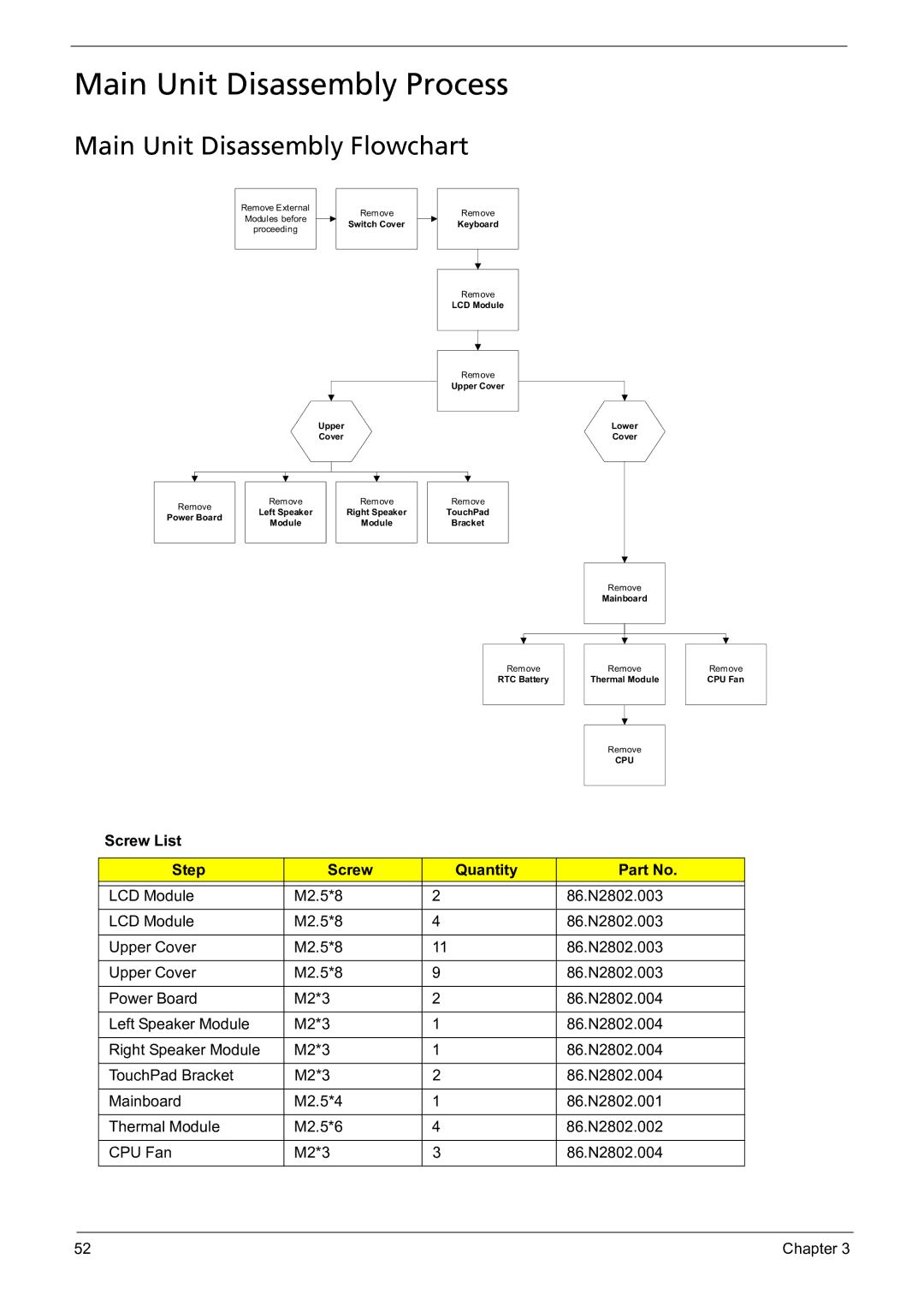
Remove External Modules before proceeding
Remove
Switch Cover
Upper
Cover
Remove
Keyboard
Remove
LCD Module
Remove
Upper Cover
Lower
Cover
Remove |
| Remove |
| Remove |
| Remove |
| Left Speaker |
| Right Speaker |
| TouchPad | |
Power Board |
|
|
| |||
| Module |
| Module |
| Bracket | |
|
|
|
| |||
|
|
|
|
|
|
|
|
| Remove | |
|
| Mainboard | |
|
|
|
|
|
|
| |
|
|
|
|
Remove |
| Remove | |
RTC Battery |
| Thermal Module | |
|
|
|
|
|
|
|
|
|
|
|
|
|
| Remove | |
|
| CPU | |
|
|
|
|
Remove
CPU Fan
Screw List
Step | Screw | Quantity | Part No. |
|
|
|
|
LCD Module | M2.5*8 | 2 | 86.N2802.003 |
|
|
|
|
LCD Module | M2.5*8 | 4 | 86.N2802.003 |
|
|
|
|
Upper Cover | M2.5*8 | 11 | 86.N2802.003 |
|
|
|
|
Upper Cover | M2.5*8 | 9 | 86.N2802.003 |
|
|
|
|
Power Board | M2*3 | 2 | 86.N2802.004 |
|
|
|
|
Left Speaker Module | M2*3 | 1 | 86.N2802.004 |
|
|
|
|
Right Speaker Module | M2*3 | 1 | 86.N2802.004 |
|
|
|
|
TouchPad Bracket | M2*3 | 2 | 86.N2802.004 |
|
|
|
|
Mainboard | M2.5*4 | 1 | 86.N2802.001 |
|
|
|
|
Thermal Module | M2.5*6 | 4 | 86.N2802.002 |
|
|
|
|
CPU Fan | M2*3 | 3 | 86.N2802.004 |
|
|
|
|
52 | Chapter 3 |