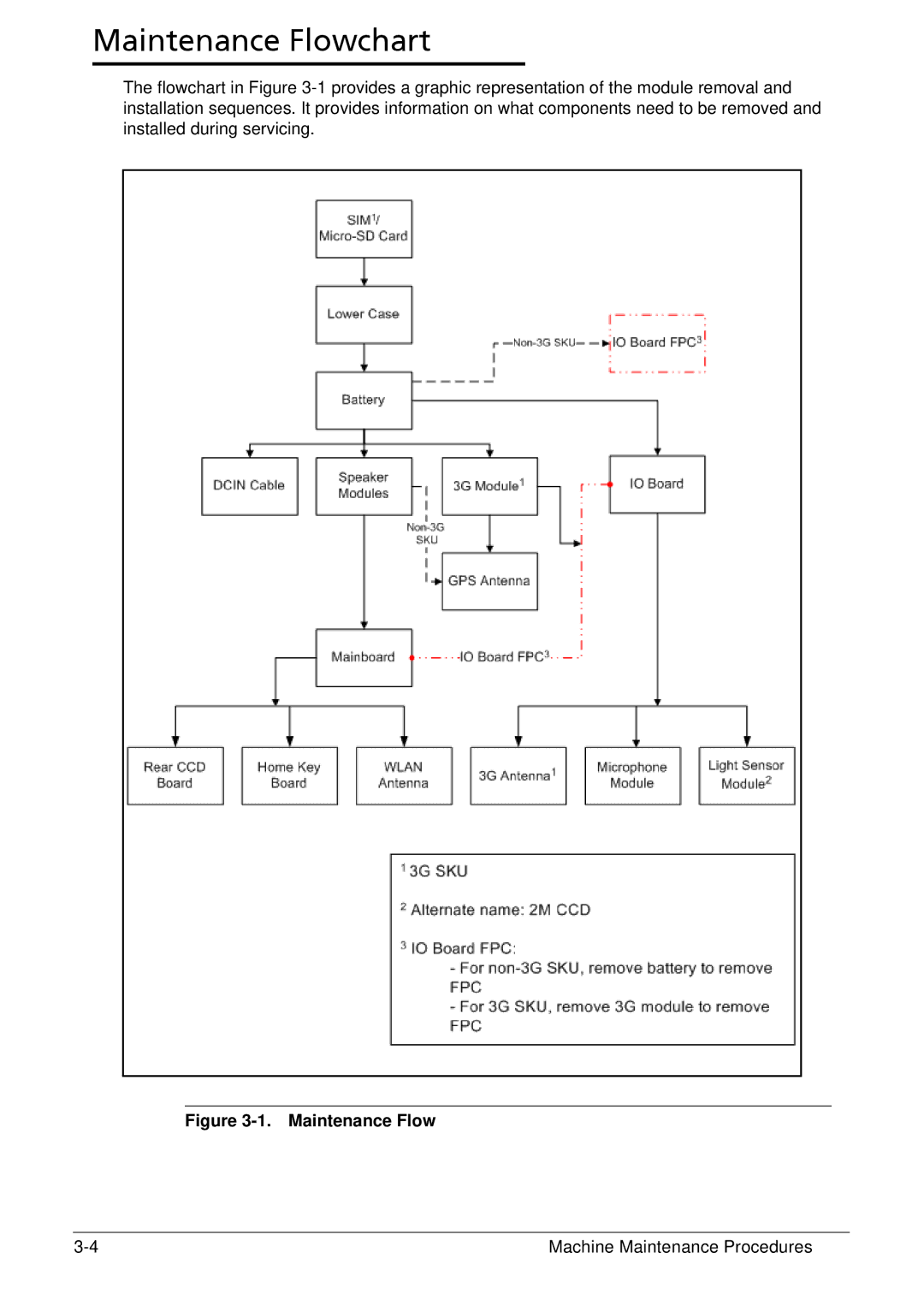
The flowchart in Figure 3-1provides a graphic representation of the module removal and installation sequences. It provides information on what components need to be removed and installed during servicing.
3-4
Machine Maintenance Procedures