Mainboard Installation
1.Install mainboard (A) on support plate. (Figure
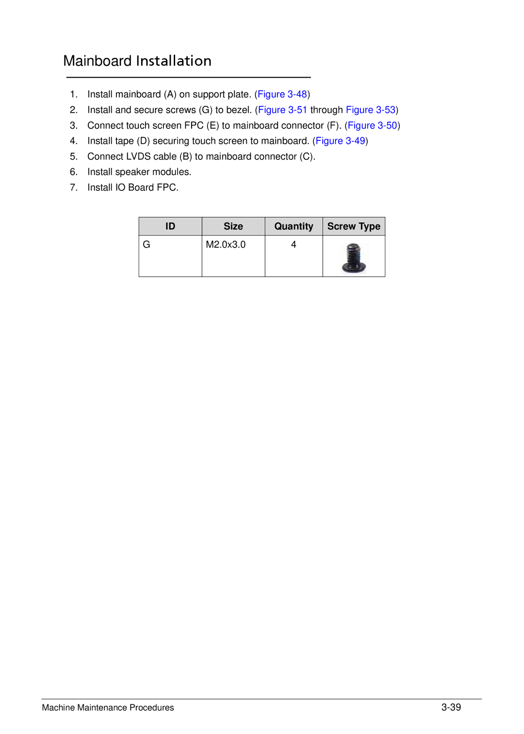
2.Install and secure screws (G) to bezel. (Figure
3.Connect touch screen FPC (E) to mainboard connector (F). (Figure
4.Install tape (D) securing touch screen to mainboard. (Figure
5.Connect LVDS cable (B) to mainboard connector (C).
6.Install speaker modules.
7.Install IO Board FPC.
ID | Size | Quantity | Screw Type |
G | M2.0x3.0 | 4 |
|
|
|
|
|
Machine Maintenance Procedures |
