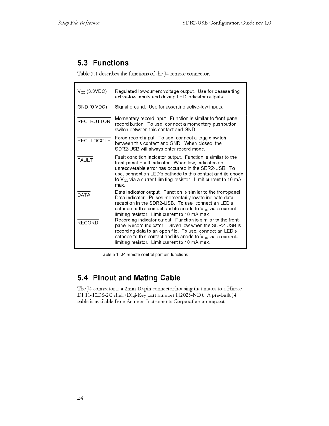
Regulated low-current voltage output. Use for deasserting active-low inputs and driving LED indicator outputs.
Signal ground. Use for asserting active-low inputs.
Momentary record input. Function is similar to front-panel record button. To use, connect a momentary pushbutton switch between this contact and GND.
Force-record input. To use, connect a toggle switch between this contact and GND. When closed, the SDR2-USB will always enter record mode.
Fault condition indicator output. Function is similar to the front-panel Fault indicator. When low, indicates an unrecoverable error has occurred in the SDR2-USB. To use, connect an LED’s cathode to this contact and its anode to VDD via a current-limiting resistor. Limit current to 10 mA max.
Data indicator output. Function is similar to the front-panel Data indicator. Pulses momentarily low to indicate data reception in the SDR2-USB. To use, connect an LED’s cathode to this contact and its anode to VDD via a current- limiting resistor. Limit current to 10 mA max.
Recording indicator output. Function is similar to the front- panel Record indicator. Driven low when the SDR2-USB is recording data to an open file. To use, connect an LED’s cathode to this contact and its anode to VDD via a current- limiting resistor. Limit current to 10 mA max.

