J4 Remote Control Port |
Contact |
| Function | Direction | Wire Color | ||||||
1 | VDD (3.3 VDC) |
| - | |||||||
2 | GND (0 VDC) |
| Black | |||||||
|
|
|
|
|
|
|
|
| ||
|
|
|
|
|
|
|
|
|
|
|
3 | REC_BUTTON | input | Blue | |||||||
|
|
|
|
|
|
|
|
|
|
|
4 | REC_TOGGLE | input | Grey | |||||||
|
|
|
|
|
|
|
|
|
| |
5 |
|
| FAULT | output | Yellow | |||||
6 | no connect |
| - | |||||||
|
|
|
|
|
|
|
|
| ||
7 |
|
|
| DATA | output | Orange | ||||
|
|
|
|
|
| |||||
8 |
| RECORD | output | Green | ||||||
9 | VDD (3.3 VDC) |
| - | |||||||
10 | GND (0 VDC) |
| - | |||||||
|
|
|
|
|
|
|
|
|
|
|
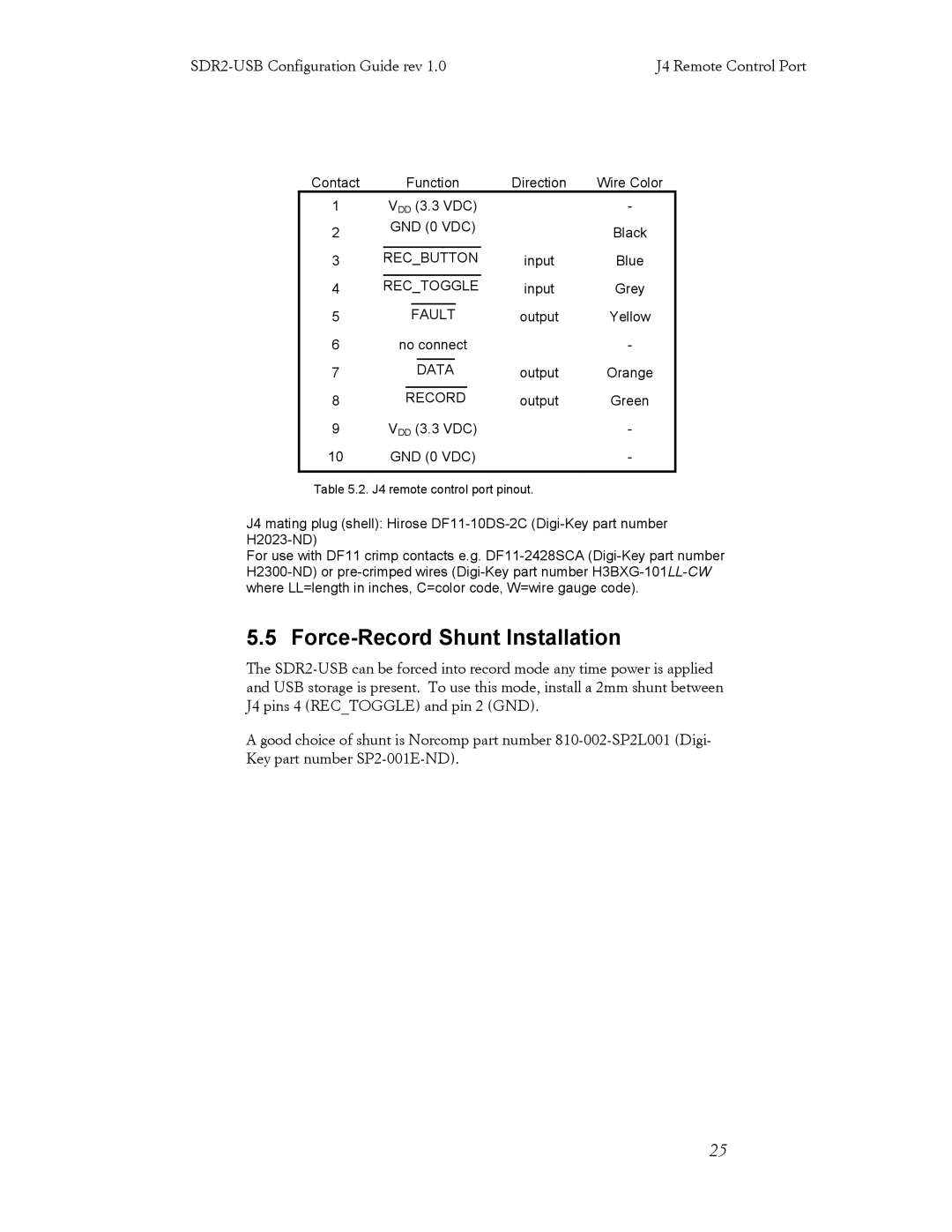
Table 5.2. J4 remote control port pinout.
J4 mating plug (shell): Hirose
For use with DF11 crimp contacts e.g.
5.5 Force-Record Shunt Installation
The
Agood choice of shunt is Norcomp part number
25
