GTP-760 specifications
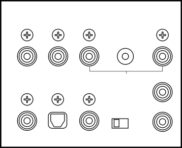
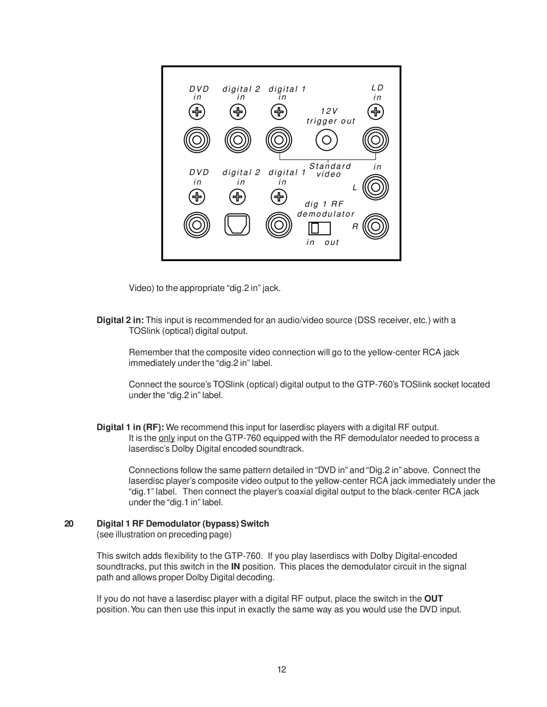
The Adcom GTP-760 is a high-performance audio/video surround processor that combines advanced technology with ease of use, delivering an exceptional home theater experience. At the heart of the GTP-760 is its extensive support for various audio formats, including Dolby Digital, DTS, and MPEG. This enables the processor to provide an immersive audio experience, allowing users to enjoy their favorite movies, music, and games with remarkable clarity.One of the standout features of the GTP-760 is its multiple input options. It comes equipped with a range of analog and digital inputs, including HDMI, allowing for seamless integration with a variety of audio and video sources. The HDMI inputs support 4K video pass-through and scaling, making the GTP-760 a future-proof option for home theater setups. Additionally, the inclusion of S-Video, composite, and component video connections ensures compatibility with older devices.
The GTP-760 also offers a comprehensive equalization system, allowing users to tailor their audio output to suit their room’s acoustics and personal preferences. The built-in audio DSP (Digital Signal Processor) delivers advanced sound processing capabilities, enhancing the overall listening experience. With customizable sound modes, users can select settings optimized for music, movies, or gaming, ensuring versatility for different content types.
User friendliness is a focal point of the GTP-760 design. The intuitive front panel controls and the ergonomic remote make navigation a breeze, while the backlit display provides clear visibility, even in low light environments. Additionally, the processor features programmable memory settings, allowing users to save different configurations for quick access.
Beyond audio performance, the GTP-760 offers robust video processing capabilities. It supports various video formats, ensuring high-quality picture output regardless of the source. The unit’s solid build quality and premium components contribute to its reliability and longevity.
In conclusion, the Adcom GTP-760 is a well-rounded surround processor that delivers outstanding sound quality and video processing capabilities. Its variety of input options, advanced audio technologies, and user-friendly design make it an excellent choice for both amateur and avid home theater enthusiasts. With its ability to enhance audio-visual experiences, the GTP-760 stands out as a remarkable addition to any entertainment system.