GTP-860 II Rear Panel
16 | 10 | 11 | 12 | 13 | 15 | 21 |
17 | 18 | 19 | 14 | 24 | 25 | 22 | 20 | 23 |
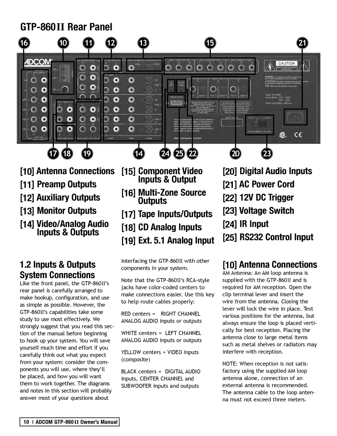
[10] Antenna Connections
[11] Preamp Outputs
[12] Auxiliary Outputs
[13] Monitor Outputs
[14] Video/Analog Audio
Inputs & Outputs
1.2Inputs & Outputs System Connections
Like the front panel, the
[15] Component Video
Inputs & Output
[16]
Outputs
[17] Tape Inputs/Outputs
[18] CD Analog Inputs
[19] Ext. 5.1 Analog Input
interfacing the
Note that the
RED centers = RIGHT CHANNEL ANALOG AUDIO inputs or outputs
WHITE centers = LEFT CHANNEL ANALOG AUDIO inputs or outputs
YELLOW centers = VIDEO inputs (composite)
BLACK centers = DIGITAL AUDIO inputs, CENTER CHANNEL and SUBWOOFER inputs and outputs
[20] Digital Audio Inputs
[21] AC Power Cord
[22] 12V DC Trigger
[23]Voltage Switch
[24]IR Input
[25]RS232 Control Input
[10] Antenna Connections
AM Antenna: An AM loop antenna is supplied with the
NOTE: When reception is not satis- factory using the supplied AM loop antenna alone, connection of an external antenna is recommended. The antenna cable to the loop anten- na must not exceed three meters.
10 ADCOM