TRACER 5045 System Manual | Section 2 Microwave Path Engineering Basics |
|
|
TRACER RSSI Test Points
The RSSI indicator for the TRACER 5045 system is provided through the VT100 terminal menus accessed through the
If the local system has acquired a useful signal from the remote system, then the remote TRACER 5045 RSSI can be viewed from the local TRACER 5045 VT100 terminal menu interface.
An RSSI test point, located on the front panel, represents the voltage (relative to the GND test point) of a relative signal level of receive strength from the far end. The voltage at this test point can vary from approximatly 0 to greater than 4 Volts DC, with 0 Volts corresponding to no signal and 4 Volts or better to full signal strength.
Antenna Beam Patterns
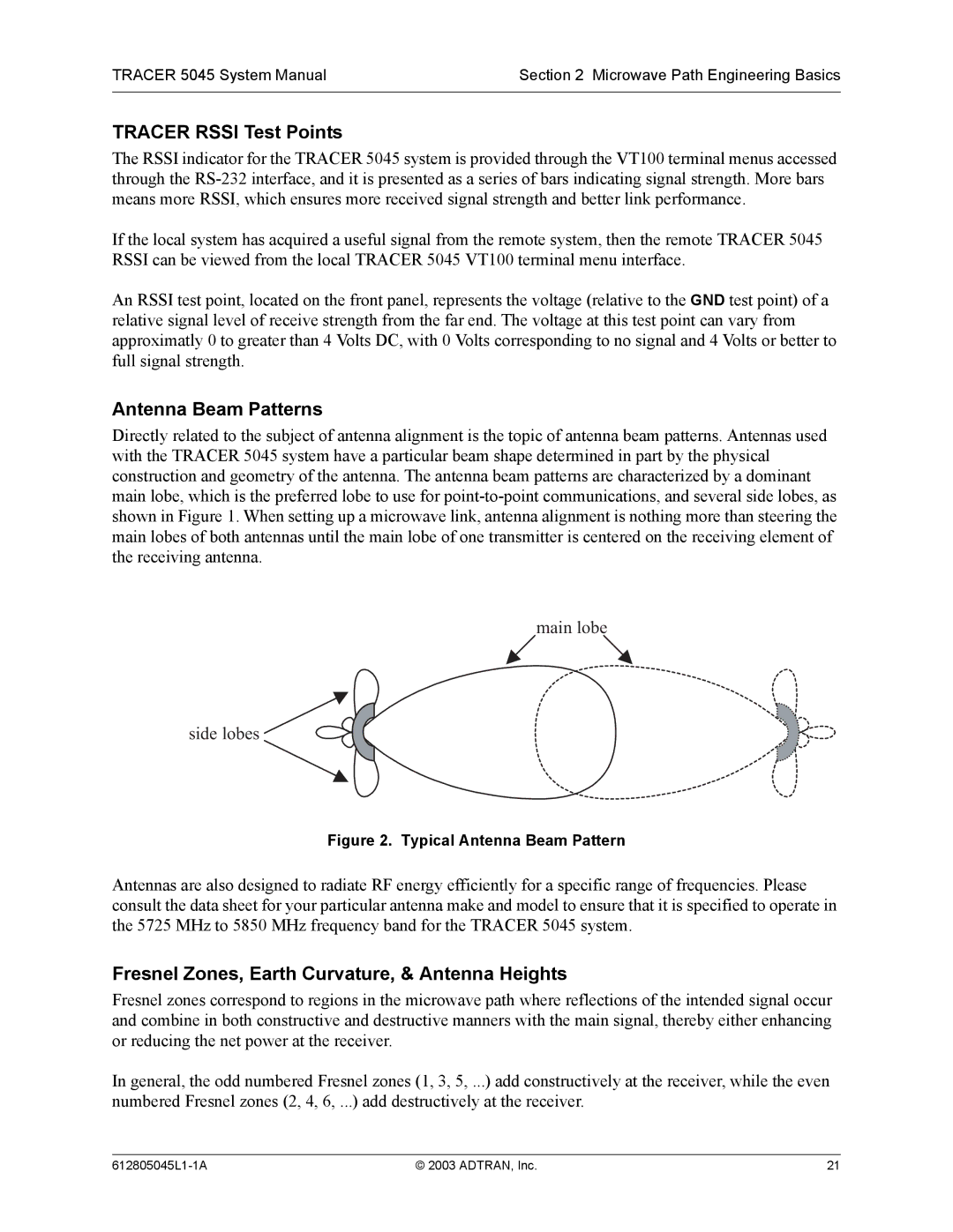
Directly related to the subject of antenna alignment is the topic of antenna beam patterns. Antennas used with the TRACER 5045 system have a particular beam shape determined in part by the physical construction and geometry of the antenna. The antenna beam patterns are characterized by a dominant main lobe, which is the preferred lobe to use for
main lobe
side lobes 

Figure 2. Typical Antenna Beam Pattern
Antennas are also designed to radiate RF energy efficiently for a specific range of frequencies. Please consult the data sheet for your particular antenna make and model to ensure that it is specified to operate in the 5725 MHz to 5850 MHz frequency band for the TRACER 5045 system.
Fresnel Zones, Earth Curvature, & Antenna Heights
Fresnel zones correspond to regions in the microwave path where reflections of the intended signal occur and combine in both constructive and destructive manners with the main signal, thereby either enhancing or reducing the net power at the receiver.
In general, the odd numbered Fresnel zones (1, 3, 5, ...) add constructively at the receiver, while the even numbered Fresnel zones (2, 4, 6, ...) add destructively at the receiver.
© 2003 ADTRAN, Inc. | 21 |