| TRACER 5045 System Manual | Section 3 Engineering Guidelines |
| |
|
|
|
|
|
|
| Table 2. TRACER 5045 LEDs |
| |
|
|
|
|
|
| For these LEDs... | This color light... | Indicates that... |
|
|
|
|
|
|
|
|
|
|
|
| PWR | Green (solid) | the TRACER 5045 is connected to a power source. |
|
|
|
|
| |
| Off | the TRACER 5045 is not currently powered up. |
| |
|
|
| ||
|
|
|
|
|
| TST | Amber (solid) | there is an active test being performed by the system. |
|
|
|
|
|
|
|
| Green | there is a valid 10/100BaseT/TX link. |
|
| LAN |
|
|
|
| Amber (blinks with activity) | there is data activity (transmit or receive data) on the |
| |
|
|
| ||
|
| 10/100BaseT/TX LAN interface. |
| |
|
|
|
| |
|
|
|
|
|
|
| Green | there is a valid wireless link. |
|
| WAN |
|
|
|
| Amber (blinks with activity) | there is data activity (transmit or receive data) over the wireless |
| |
|
|
| ||
|
| link. |
| |
|
|
|
| |
|
|
|
|
|
| PLAN A | Green (solid) | the TRACER 5045 is transmitting on Frequency Plan A. |
|
|
|
|
| |
| Off | the TRACER 5045 is not transmitting on Frequency Plan A. |
| |
|
|
| ||
|
|
|
|
|
| PLAN B | Green (solid) | the TRACER 5045 is transmitting on Frequency Plan B. |
|
|
|
|
| |
| Off | the TRACER 5045 is not transmitting on Frequency Plan B. |
| |
|
|
| ||
|
|
|
|
|
| RF LOW | Red (solid) | the RSSI level is below suggested minimum threshold |
|
| (approximately 10 dBm above the minimum receive sensitivity). |
| ||
|
|
|
| |
|
|
|
|
|
| RF DOWN | Red (solid) | there is a communication problem between the local and remote |
|
| TRACER 5045 systems. |
| ||
|
|
|
| |
|
|
|
|
|
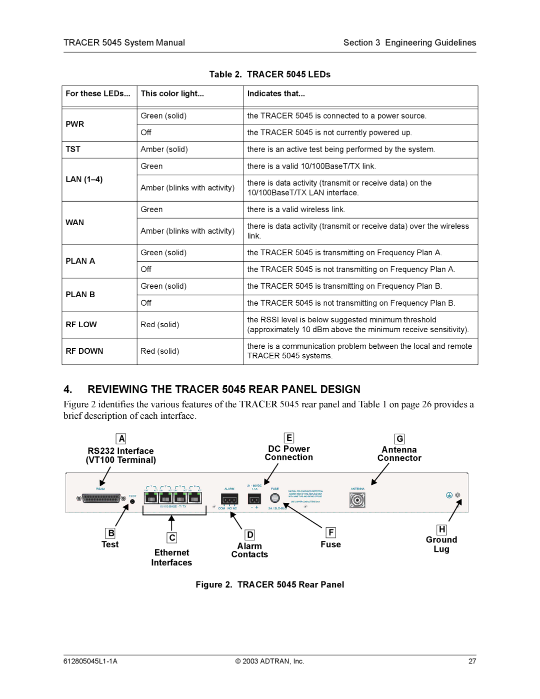
4.REVIEWING THE TRACER 5045 REAR PANEL DESIGN
Figure 2 identifies the various features of the TRACER 5045 rear panel and Table 1 on page 26 provides a brief description of each interface.
A | E | G |
RS232 Interface | DC Power | Antenna |
(VT100 Terminal) | Connection | Connector |
1 |
| 2 | 3 | 4 |
LNK | ACT LNK | ACT LNK | ACT LNK | ACT |
| 10/100 BASE - T/ TX |
| ||
B |
|
| D | F | H | |
C | ||||||
Ground | ||||||
Test | Ethernet | Alarm | Fuse | Lug | ||
| Contacts |
|
| |||
Interfaces
Figure 2. TRACER 5045 Rear Panel
© 2003 ADTRAN, Inc. | 27 |