PCA-6186
User’s Manual
Copyright Notice
Advantech customer services
Message to the Customer
PCA
Product warranty
Initial Inspection
Contents
Chapter Award Bios Setup
Advanced Chipset Features
Chapter Chipset Software Installation Utility
Chapter
External Keyboard Connector CN12 109
General Information
Hardware Configuration
Introduction
Features
Memory
Specifications
System
Input/Output
VGA interface
Industrial features
Mechanical and environmental specifications
Ethernet LAN
Jumpers and Connectors
Connectors
PIN1 Smbdata
Board Layout Jumper and Connector Locations
Jumper and connecter locations
Extension I/O daughter board for PCA-6186E2-00A1
Safety Precautions
Jumper Settings
How to set jumpers
Watchdog timer output J2
Cmos clear J1
System Memory
Memory Installation Procedures
Cache Memory
Sample calculation Dimm memory capacity
CPU Installation
Connecting Peripherals
Primary CN1 and Secondary CN2 IDE Connec Tors
Floppy Drive Connector CN3
Parallel Port CN4
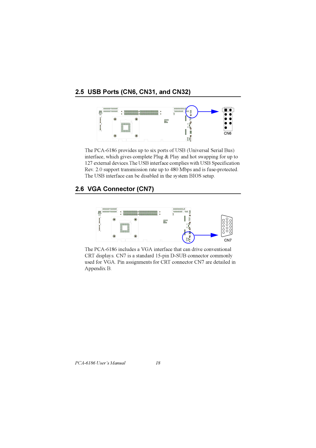
VGA Connector CN7
USB Ports CN6, CN31, and CN32
10/100Base-T Ethernet Connectors CN8 and CN34
Serial Ports CN9 COM1 CN10 COM2
PS/2 Keyboard and Mouse Connectors CN11 and CN33
External Keyboard Connector CN12
Infrared IR Connector CN13
CPU Fan Connector CN14
Front Panel Connectors CN16, 17, 18, 19, 21&22
Power LED and Keyboard Lock CN16
External speaker CN17
ATX soft power switch CN21
ATX Power Control Connectors CN20
Reset CN18
HDD LED CN19
SM Bus Connector CN29
Controlling the soft power switch
Connecting to SNMP-1000 remote manager
Auxiliary 4-pin power connector CN46 and CN47
17 AC-97 Audio Interface
PCA-6186 User’s Manual
Award Bios Setup
Entering Setup
Award Bios Setup initial screen
Standard Cmos Setup
Cmos RAM backup
Advanced Bios Features
Advanced Bios features screen
Boot UP Floppy Seek
Quick Power On Self Test
First/Second/Third/Other Boot Device
Boot Up NumLock Status
Security Option
Typematic Delay msec
Apic Mode
MPS Version Control For OS
Dram Timing Selectable
Advanced Chipset Features
Active to Precharge Delay
CAS Latency Time
Video Bios Cacheable
Dram RAS# to CAS# Delay
System Bios Cacheable
Delayed Transaction
Integrated Peripherals
Boot Display
IDE Primary Secondary Master/Slave PIO/UDMA Mode
On-Chip Frame Buffer Size
USB Keyboard/Mouse Support
IDE HDD Block Mode
USB Controller
5 AC97 Audio
16 UR2 Duplex Mode
Uart Mode Select
IR Transmission Delay
Parallel Port Mode
ECP Mode Use DMA
Power Management Setup
EPP Mode Select
Power-Supply Type