OPERATING MANUAL
AGILENT 603xA FAMILY AUTORANGING SYSTEM DC POWER SUPPLIES
LIMITATION OF WARRANTY
WARRANTY
CERTIFICATION
EXCLUSIVE REMEDIES
Safety Summary
SAFETY SYMBOLS
Declaration Page
DECLARATION OF CONFORMITY
Herstellerbescheinigung
Acoustic Noise Statement
Manufacturer’s Declaration
Installation
Table Of Contents
General Information
Operating Instructions
Table Of Contents continued
100 VAC Input Power Option
Table Of Contents continued
Standard Commands for Programmable Instruments
Blank Front Panel Option
Programming the Agilent 603xA Power Supplies Using BASIC
Table Of Contents continued
Index
Introduction
General Information
Description
Accessories
Safety Considerations
Options
Option
Instrument and Manual Identification
GP-IB Compatibility
GP-IB Interconnection Cables and Connectors
Ordering Additional Manuals
Model
Related Documents
Specifications
Table 1-2. Supplemental Characteristics
Table 1-1. Performance Specifications
Agilent Technologies Model
6033A
6031A
6030A
6032A
6035A
18 General Information
Table 1-2. Supplemental Characteristics continued
Agilent Model
Figure 1-1. Output Characteristic Curve
6030A
6031A
20 General Information
Initial Inspection
Installation
Preparation For Use
Outline Diagram
Input Power Requirements
Figure 2-1. Outline Diagram Bench Operation
Power Connection
22 Installation
Figure 2-2. Power-Cord Plug Configurations
Line Voltage Option Conversion
f. Change line label
Figure 2-3. Line Voltage Conversion Components
26 Installation
Repackaging For Shipment
AC Line Impedance Check
Rear Panel Screw Sizes and Part Numbers
Agilent Models 6030A, 6031A, 6032A, 6035A
Agilent Model 6033A
28 Installation
Agilent Model 6038A
Figure 2-4. Part Number Location
Figure 3-1. Front-Panel Controls and Indicators
OPERATING INSTRUCTIONS
Introduction
Output Range For An Autoranging Power Supply
Controls and Indicators
Figure 3-2. Determining Operating Point
Table 3-1. Controls and Indicators
Controls/Indicators
Number
Figure 3-3. Overrange Operation
Controls/Indicators
Table 3-1. Controls and Indicators continued
Number
Description
Table 3-1. Controls and Indicators continued
Turn-On Checkout Procedure
Controls/Indicators
Number
Figure 3-4. Factory Settings, Mode Switch
Connecting the Load
Initial Setup and Interconnections
maximum length =
Table 3-2. Maximum Wire Lengths To Limit Voltage Drops
current x resistivity
Cross Section Area In mm2
Cross Section Area in mm2
Table 3-3. Stranded Copper Wire Ampacity Wire Size
Ampacity
Figure 3-5. Connecting a Bypass Capacitor Overvoltage Protection OVP
Foldback Protection
Remote Voltage Sensing
2Rs +.5 1000
Mode Switches
Figure 3-6. Remote Voltage Sensing
Table 3-4. Mode Switches
Mode Switches
Figure 3-7. GP-IB Connector
Programming Mode
Protective Circuits
Monitor Signals
Constant Voltage Operation
Local Operation
Constant Current Operation
GP-IB Operation
Return to Local
Interface Functions
Multiline Message Control Functions. The Acceptor Handshake, Source Handshake, Listener, and Talker functions are implemented by the interface circuits of the power supply and the controller and require no action by the user. The LSN or TLK indicators turn on when the power supply is addressed to listen or talk. The talker function includes serial poll, see below
Table 3-5. Serial Poll Register
GP-IB Address Selection
INH-FLT or RLY LNK Operation
Power-On Service Request
Figure 3-8. GP-IB Address/PON SRQ Switches
Initial Conditions
Table 3-6. Initial Conditions
Programming Syntax
+ 1.23 E + 4 + 123. E +
Table 3-7 GP-IB Commands
Command
Range or **Response
To Query
Table 3-7 GP-IB Commands continued
Command
Range or **Response
Page
Table 3-7 GP-IB Commands continued
Command
Range or **Response
Page
Table 3-7 GP-IB Commands continued
Command
Range or **Response
Page
Table 3-7 GP-IB Commands continued
Command
Range or **Response
Page
Table 3-8. Format of Numbers Sent from Power Supply
VSET? and addressing the power supply to talk
VMAX
OUT OFF or OUT OUT ON or OUT
Hold is turned on and off using these codes HOLD OFF or HOLD
60 Operating Instructions
Table 3-9. Status Register
Bit Weight
Bit Position
Condition
62 Operating Instructions
SRQ?
Table 3-10. Status Register Errors Description
Error #
No Errors
Analog Programming
66 Operating Instructions
Figure 3-9. Resistance Programming of Output Voltage
Figure 3-10. Voltage Programming of Output Voltage
Multiple-Supply Operation
Figure 3-11. Optional Voltage Divide for Program Source
Figure 3-13. Voltage Programming of Output Current
Figure 3-12. Resistance Programming of Output Current
Auto-Parallel Operation
68 Operating Instructions
Series Operation
Figure 3-14. Auto-Parallel Operation
Figure 3-15. Series Operation
Fault Input FLT and Remote Inhibit INH Connections
Figure 3-18. FLT Example
Figure 3-16. FLT/INH Connections Figure 3-17. INH Example
Operating Instructions
Figure 3-19a. FLT and INH with Multiple Supplies
Figure 3-19b. Typical INH Setup
72 Operating Instructions
Figure 3-20. Timing Diagram Figure 3-21. FLT & INH Example
Using Appendix A
100 VAC Input Power Option
General Information Description
Scope of Appendix A
Section lll Manual Changes
Section ll Manual Changes
Agilent Model
Set a
100 VAC Input Power Option 100
Turn-On Check Out Procedure
Blank Front Panel Option
Introduction
Description
Agilent 6030A Agilent 6031A Agilent 6032A Agilent 6033A
Overvoltage Protection Setting
Table B-2. CC Check Command String
Agilent Model
String
ABOUT THIS APPENDIX
Standard Commands for Programmable Instruments SCPI
READER PATH
REFERENCES
INTRODUCTION
LANGUAGE SWITCHING
STAND-ALONE CONNECTIONS
Installation
LINKED CONNECTIONS
Figure C-1 Linked Connections
Addressing Over the Bus
Setting the Address
GP-IB Address
Type of Connection
COMMON Commands
LANGUAGE DICTIONARY
Subsystem Commands
Keywords
Figure C-3. Agilent Series 663xA Subsystem Tree Diagram
Figure C-2. Common Command Syntax Diagram
88 Standard Commands for Programmable Instruments SCPI
Bit Configuration of Standard Event Status Enable Register
Event Status Enable
Meaning and Type
Clear Status Device Status
IDN?
ESR?
0 to
Meaning and Type
Power-on Status Clear
OPC?
Description
Pending operations are complete when
0 or
0 or l
Meaning and Type
Description
Meaning and Type
Reset
Device State
Description
Service Request Enable
STB?
Bit Configuration of Status Byte Register
Meaning and Type
ABOR
TST?
Meaning and Type
Trigger
CURRLEV
Current Subsystem
CURRPROTSTAT
0 or OFF
Measure Subsystem
Initiate Subsystem
Output Subsystem
For INITCONT 0 or OFF 1 or ON
I or ON
0 or OFF
0 or
CRD NORMal or REVerse
Bit Configuration of Operation Registers
Status Subsystem
Status Operation Registers
0 to
STATUS PRESET
NTR/PTR Commands
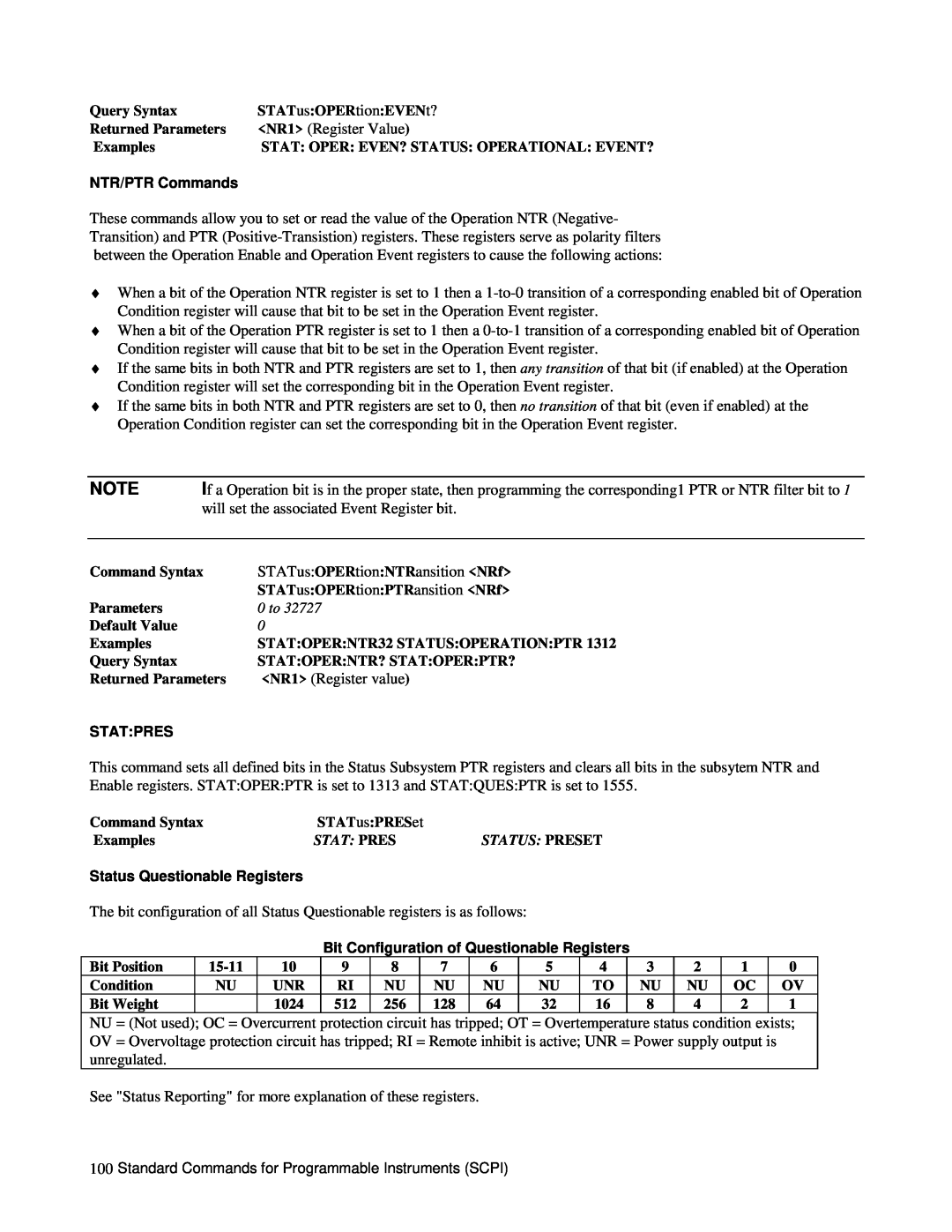
Bit Configuration of Questionable Registers
0 to
STATQUESCOND?
NTR/PTR Commands
STATQUESENAB
0 to
SYSTLANG
SYSTERR?
0 to
Syntax is the same, regardless of the present language
Voltage Subsystem
Trigger Subsystem
TRIGSOUR
VOLTPROTAMPL?
STATUS REPORTING
Table C-5. Bit Configuration of Status Reister Groups Meaning
Signal
Status Byte and Service Request Enable Registers
Operation Status Group
Table C-2. STATQUES Commands
Figure C-4. Power Supply Status Structure
Command
Register
Enable
Signal
Table C-4. STATOPER Commands
Command
Enables all error conditions into the ESB summary bit
Service Request Enable Register
Program Command
Clear Command
Output Queue
SCPI ERROR MESSAGES
Enables all bits to generate seruice requests
Excludes the MAV bit from gerlerating a service request
Table C-5. Summary of Error Messages
Error Number
Error String Description/Explanation/Examples
Table C-5. Summary of Error Messages continued
Error Number
Error String Description/Explanation/Examples
SCPI COMMAND SUMMARY
Command
Command Summary continued Subsystem Commands
Command
Command
Table C-6. Comparison of ARPS and SCPI Commands
ARPS/SCPI Commands
ARPS Command
Equivalent SCPI Command
I/O Path Names
Programming the Agilent 603xA Power Supplies Using Basic
Initialization
Voltage and Current Programming
Voltage and Current Readback
120 130 DEF FNSettledOPTIONAL Band, Rdgs.Timelimit
Power Supply Status
Output Inhibit / Enable
Present Status
FOLD
Accumulated Status
Serial Poll
Fault and Mask Registers
Page
Service Request
Programming Error Detection
Delay Time
Explanation
124 Programming the Agilent 603xA Power Supplies Using Basic
Fault Indicator FLT and Inhibit INH
Protection Functions
Overvoltage
Foldback
Hold Mode
Advanced Topics
Machines States
Explanation
Programming the Agilent 603xA Power Supplies Using Basic
Index
Index
Index
CC bit
130 Index
Index
Index
output enable
OPC bit
132 Index
United States
Agilent Sales and Support Office
Canada
Europe
Manual Updates