It is not recommended that Agilent 6035A supplies be connected in series. if you do so, the common connection between the two supplies must be connected to earth ground (see Figure
Add the voltage settings of each power supply together to determine the total output voltage. Set the current limits for each power supply to the maximum that the load can handle without damage.
![]() When two supplies are operated in series, they should be programmed to the same voltage to prevent possible damage to the lower voltage supply during short circuit conditions. Contact the factory if this is not possible.
When two supplies are operated in series, they should be programmed to the same voltage to prevent possible damage to the lower voltage supply during short circuit conditions. Contact the factory if this is not possible.
Fault Input (FLT) and Remote Inhibit (INH) Connections
The connections for FLT and INH are made through a connector which is located on the rear of the power supply just below the
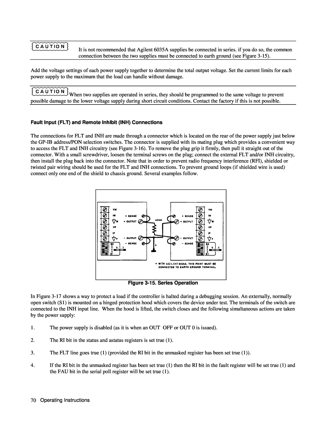
Figure 3-15. Series Operation
In Figure
1.The power supply is disabled (as it is when an OUT OFF or OUT 0 is issued).
2.The RI bit in the status and astatus registers is set true (1).
3.The FLT line goes true (1) (provided the RI bit in the unmasked register has been set true (1)).
4.If the RI bit in the unmasked register has been set true (1) then the RI bit in the fault register will be set true (1) and the FAU bit in the serial poll register will be set true (1).
70Operating Instructions