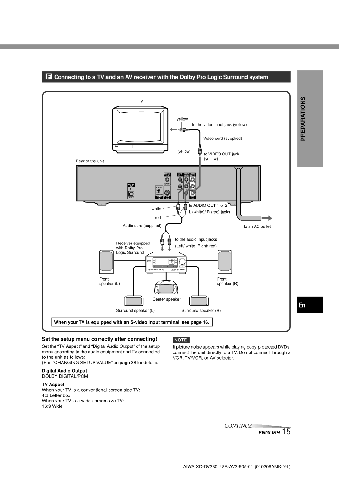
F Connecting to a TV and an AV receiver with the Dolby Pro Logic Surround system
TV
|
| yellow |
| |
|
|
|
| to the video input jack (yellow) |
|
|
|
| Video cord (supplied) |
|
| yellow | to VIDEO OUT jack | |
|
|
|
| |
Rear of the unit |
|
|
| (yellow) |
|
|
|
| |
| DIGITAL | AUDIO | COMPONENT | AUDIO |
| OUT | OUT 2 | VIDEO OUT | OUT 1 |
| COAXIAL | L | Pb | L |
DIGITAL |
|
|
| |
OUT |
|
|
|
|
| R | Pr | R | |
|
| |||
| COMPONENT |
| Y |
|
| VIDEO | VIDEO | ||
OPTICAL |
| |||
OUT | OUT |
| OUT |
PREPARATIONS
white
red
Audio cord (supplied)
Receiver equipped with Dolby Pro Logic Surround
![]() to AUDIO OUT 1 or 2
to AUDIO OUT 1 or 2 ![]()
L (white)/ R (red) jacks
to an AC outlet
to the audio input jacks
(Left/ white, Right/ red)
Front | Front |
speaker (L) | speaker (R) |
Center speaker |
|
Surround speaker (L) | Surround speaker (R) |
When your TV is equipped with an
En
Set the setup menu correctly after connecting!
Set the “TV Aspect” and “Digital Audio Output” of the setup menu according to the audio equipment and TV connected to the unit as follows:
(See “CHANGING SETUP VALUE” on page 38 for details.)
Digital Audio Output
DOLBY DIGITAL/PCM
TV Aspect
When your TV is a
When your TV is a
NOTE
If picture noise appears while playing
CONTINUE
ENGLISH 15
AIWA
