Alesis M20 Professional 20-BIT Digital Recorder
Alesis M20 Reference Manual
Table of Contents
Table of Contents
Tape Formatting
Track Record Enabling and Monitoring
Digital/Analog Input Selection and Routing
Autolocation
Varispeed SMPTE, Sync, and Offset Functions
Midi Functions
Utility Menu
LRC Remote Control Tutorials and Applications
M20 Smpte Synchronization Overview
Maintenance and Troubleshooting
Using The M20 Data Section Of Tape
Time Code Tutorial
M20 Hidden Functions
Table of Contents
Please Follow These Precautions When Using this Product
Important Safety Instructions and Compliance
Safety Symbols Used in this Product
Viii
Instructions DE Sécurité Importantes
Symboles Utilisés Dans CE Produit
Safety Notices
Safety Notices
ICES-003 Issue
CE Declaration of Conformity
M20 Highlights
OVERVIEW, SETUP, and Basics
Chapter
Unpacking and Inspection
AC Power Hookup
Overview, Setup and Basics, Chapter
Line Conditioners and Protectors
About Audio Cables
Backup
Basic Audio Hookup
USE the Right Tape
Preparing the Tape Prior to USE
Avoid Electromagnetic Interference
Overview, Setup and Basics
Operating Environment
M20 Front Panel
Control and Connector Basics
About the Front Panel
Control and Connector Basics, Chapter
M20 Rear Panel with optional EC-1 AES/EBU Card
About the Rear Panel
2L Power
2I Midi in and OUT
2G Video in and Thru
2H Adat Sync in and OUT
Editing M20 Operating Parameters
Keypad
Editing M20 Parameters, Chapter
To customize the default set of names
1F ENTER/NAME
1G Selecting Pages
1H Selecting page Parameters
1I Entering Parameter Values
Editing M20 Parameters
Edit Button
Editing Conventions
Tape Formatting
Sample Rate Selection
Formatting Tape, Chapter
Formatting Tape
Word Length Selection
1A PULL-UP and PULL-DOWN Sample Rate Selection
Format a NEW Tape
Record Tracks While Formatting
Extend a PARTIALLY-FORMATTED Tape
END Formatting
Certify Tape Format
Reformatting Caution
Recording a Benchmark Tape
Lock OUT Formatting Safe Mode
Bulk Erasing
Track Record Enabling and Monitoring
Track Basics
Track Input Enables
Auto Input Switch
Record Enable
Track Record Enabling and Monitoring, Chapter
Safety Mode ALL Safe
Monitor Inputs ALL Input
Track Record Enabling and Monitoring, Chapter
Input Select
DIGITAL/ANALOG Input Selection and Routing
Digital Source
Input Selection and Routing, Chapter
Input Signal Routing Analog and Digital
Track Output Selection
4A Analog Input Routing
Input Selection and Routing
4B Digital Input Routing
If digital source = Adat Optical
If digital source = I/O Card AES/EBU
If digital source = Track Copy
4C RECORD-ENABLING the Destination Tracks
AUX Routing Input and Output
1A Clearing Peaks
Meter Mode Selection
Metering
Meter Setup
Metering, Chapter
Transport Controls and Basic Recording
About the Tape Counter
4A JOG Mode
JOG/SHUTTLE Wheel and Search
3A Play Button and Sync Status
Transport Controls and Basic Recording, Chapter
4B Shuttle Mode
4C Search Button
4D Search Master
Other Transport Buttons
You press… If tape is If tape is moving You see… Stopped
6B Punching OUT of Record
Record
6A Punching Into Record
Rehearse Mode
6D Recording with a Footswitch
How to Override Write-Protection
6C Record WRITE-PROTECTION
8A Setting Auto Record Punch Points
Auto Record
8B Enable Auto Record
8C SET Auto Punch Points on the FLY
Transport Controls and Basic Recording, Chapter
Autolocation
ENTERING, SELECTING, and Editing Location Points
1A SET Locate
1B Copy Tape Location
Autolocation, Chapter
To select and edit location points
Loop Between Start and END Locate Points Auto Return
Deferred Play and Record
PLAY-AFTER-LOCATE Auto Play
4A Setting Loop Start and END Points
SET PRE-ROLL
SET POST-ROLL
FOOTSWITCH-CONTROLLED Location
Varispeed
10-1
Varispeed, Chapter 10-2
11-1
SMPTE, SYNC, and Offset Functions
Clock Source
Smpte Rate
Time Code Source
11.3A Internal
SMPTE, Sync, and Offset, Chapter
11-3
Chase Reference
SMPTE, Sync and Offset
Smpte Chase
Reference Counter
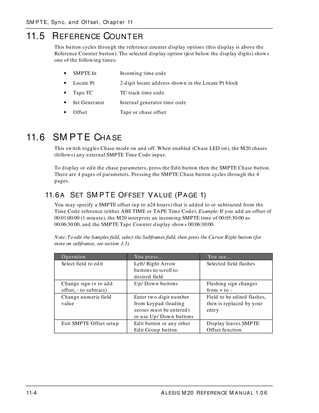
11.6A SET Smpte Offset Value
11-4
11.6B SET Smpte Chase Mode
11.6C SET Flywheel Duration
11.6D Park Ahead
11-5
11-6
11.7A Generator Mode
Internal Generator
11-7
11.7B Time Code Start Reference
11.7C ABS/START Offset
Tape Offset
11-8
Hmsfsf
11-9
Track Delay
11-10
To change delay for several tracks at once
11-11
SMPTE, Sync, and Offset, Chapter 11-12
Midi Functions
Midi Device
MMC Output
MTC Follow GEN
Receive Sysex DUMP?
Send SOFTWARE?
Load SOFTWARE?
Approximately 12 minutes
12-3
Midi Functions, Chapter 12-4
Utility Menu
Digital OUT
Online Source
13.2A Online Button
13.2B Independent Slave Mode
Online Control
ONE-BUTTON Record
Input Monitor
Unthread Timeout
Crossfade Time
Time Code Output Level
REWIND/FAST Forward TC Output
Search Enable
Locate Before Play
Mute Until Lock
Dynamic Punch
Load Data from TAPE?
13-5
13-6
Front Panel Software Version
Software Version
LRC Remote Control
14-1
LRC Remote Control, Chapter 14-2
Tutorials and Applications
Tutorial 1 Multiple M20 Operation
Overview
Synchronizing Machines
Independent Slave Mode
MASTER/SLAVE Interaction
Achieving Lock
Tutorials and Applications, Chapter
Master Format ENABLED, Complete Format
Master Format ENABLED, Format Extend
Formatting Multiple Tapes
15-3
15-4
Master Format Disabled
Master Format DISABLED, Format Extend
Tutorial 2 Making Digital Backups
15-5
15-6
Dealing with Damaged Tape
Making a 16-BIT Copy from a 20-BIT Master
15-7
Tutorial 3 Recording Digital Audio from Other Sources
Digital Clock Considerations
Tutorial 4 Combining M20S and Adats
M20 Transport Speed
Sample Rate VS. Pitch Control
Input Monitoring
Polarity Differences
15-9
Tutorial 5 Setting UP Inputs
15-10
Tutorial 6 Updating M20 Software
15-11
Tutorial 7 Using the M20 with Unbalanced Inputs and Outputs
15-12
Synchronization Overview
Synchronization Basics
Chapter
Master or SLAVE?
ONE Clock Principle
16.2A House Sync
16.2B Genlocked Time Code
Smpte Synchronization Overview, Chapter
Reference Counters VS. Clock Sources
16.3A Location Reference
16.3B Reference Clock
Smpte Synchronization Overview
16-4
16-5
Offsets in the M20
16.3A Smpte Chase Offset
16-6
16.3B Internal Generator ABS Offset
16.3C Tape Offset
Smpte Time Code Rates and Types
16.4A Drop Frame
16.4B AUTO-DETECTION of Smpte Rates
16-7
16-8
16.4D MTC Midi Time Code
16.4C Vitc Vertical Interval Time Code
Time Code Tutorial
Generating Time Code Onto a VCR
Press Edit to leave edit mode. The blue light will turn off
17-1
Synchronizing Without a T/C Track
Time Code Tutorial, Chapter
Press INT GEN or TC Input to stop the time code generator
17-2
Recording a Time Code Track
17.3A Recording Smpte from ABS Time
Leave Edit mode, turn on INT GEN, and arm the TC track
17-3
Press Play and Record
18-5
Maintenance Troubleshooting
Adat Head Cleaning
Maintenance and Troubleshooting, Chapter
18.1A Head Cleaning Cassettes Optional
18.1B Manual Head and Tape Path Cleaning
18-7
Adat Head Life
18.2A Head Alignment
Tape Maintenance Safe Tape
18.3A Tape Wear
18.3B Care of Adat Tapes
18-8
MAINTENANCE/SERVICE
18.4A Exterior Cleaning
18.4B Maintenance
18.4C Refer ALL Servicing to Alesis
18-10
18.4D Obtaining Repair Service
Customers in the USA
POWER-ON Button Combinations
M20 Hidden Functions
Miscellaneous Button Combinations
Appendix
Appendix 1, M20 Hidden Functions A1-2
MA-3
Advanced Functions
M20 Software Version
Page
Using the M20 Data Section of Tape
BRC ⇔ M20 Song Start / Smpte Start Offset
General Data Section Convention on the M20
M20 Locate Points and Smpte Offsets
A2-2
Appendix 2, Using The M20 Data Section Of Tape
BRC ⇔ M20 Parameter MAP
Appendix 2, Using The M20 Data Section Tape
A2-3
Appendix 2, Using The M20 Data Section Of Tape A2-4
M20 Transport System Error Messages
A3-1
Appendix 3, M20 Transport & System Error Messages
A3-2
Capstan State Transition Errors
A3-3
Deck State Transition Errors
A3-4
Other Errors Messages
A3-5
Appendix 3, M20 Transport & System Error Messages A3-6
M20 Major Feature Update Version
RS-422 Sony 9-PINSLAVE Operation
RS-422 Track ARM ON/OFF
RS-422 Mapping 1-2, ODDEVN, Local
Storing Locate Points When ID 1 is Offline
ID 1 Offline with the Cadi Remote
M20 master and two slaves ID 1 à ID 2 à ID
Cadi with M20 master and two slaves Cadi à ID 1 à ID 2 à ID
Special notes when operating a Cadi with ID 1 offline
Tape TC Detection in Fast Wind Modes
MA-4
Fixed Mode Time Code Generation TC Start REF
Tape TC in the Tape Counter
Tape TC Updating When in Input Mode
Card AS the Digital Source
Smpte Chase with the Stop Button
VARI-SPEED and PULL-UP/DOWN
Midi Thru
NEW Utility page Order
Cadi Display Changes
Cassette AUTO-INJECT
NEW RS-422 Device ID