CHAPTER 4: INSTALLING AND REPLACING COMPONENTS
3
2
1
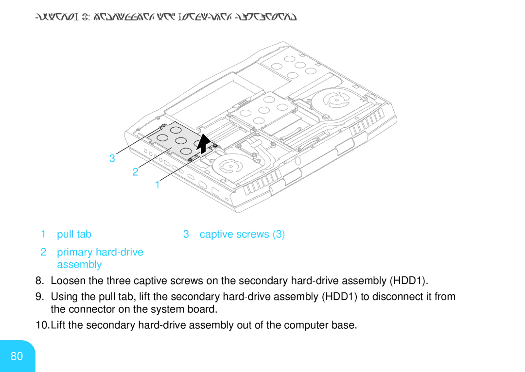
1 pull tab | 3 captive screws (3) |
2primary hard-drive assembly
8.Loosen the three captive screws on the secondary
9.Using the pull tab, lift the secondary
10.Lift the secondary
80