Supply relay 1 controls terminals 1 and 2. Figure 36 shows the jumper wire from terminal 13 (L1 220 VAC) to all other even pins (i.e., 2, 4, 6…). This applies L1 (220 VAC) to terminal 2. When supply 4 on the
IMPORTANT: Supply 4 must be programmed on the
IMPORTANT: The
Installation
Primary 220 Volt Remote Liquid Supply Connection (Continued)
EXAMPLE: PUMPS 24V ~ |
CFSD518N |
CFD518N |
Figure 37
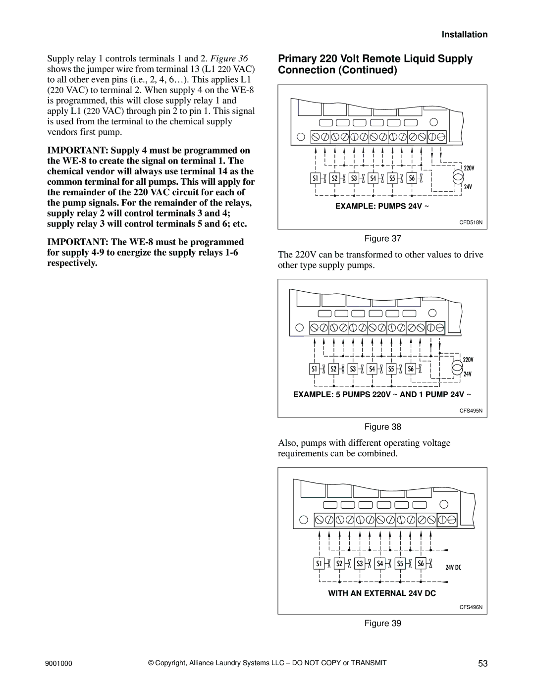
The 220V can be transformed to other values to drive other type supply pumps.
EXAMPLE: 5 PUMPS 220V ~ AND 1 PUMP 24V ~ |
CFS495N |
CFS495N |
Figure 38
Also, pumps with different operating voltage requirements can be combined.
WITH AN EXTERNAL 24V DC |
CFS496N |
Figure 39
9001000 | © Copyright, Alliance Laundry Systems LLC – DO NOT COPY or TRANSMIT | 53 |