Manuals
/
Allied Air Enterprises
/
Household Appliance
/
Heat Pump
Allied Air Enterprises
4HP16LT
manual
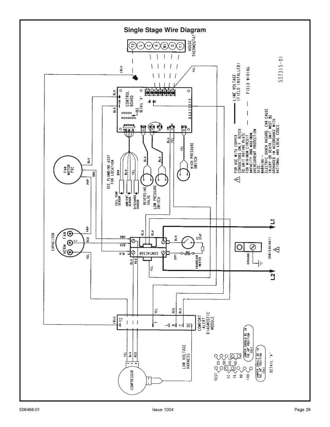
Single Stage Wire Diagram
Models:
4HP16LT
1
29
30
30
Download
30 pages
11.16 Kb
23
24
25
26
27
28
29
30
Install
Single Stage Wire Diagram
Delay Mode
Electrical Wiring
Maintenance
System Diagnostic Module
Brazing Connection Procedure
Refrigerant Charge Adjustment
Case of extended power outage
Service Valve
Page 29
Image 29
Single Stage Wire Diagram
506468-01
Issue 1004
Page 29
Page 28
Page 30
Page 29
Image 29
Page 28
Page 30
Contents
4HP16LT Series
Torque Table
Installation Clearances
General
Fastener Torque
Slab Mounting
Electrical Wiring
Slab Mounting
Roof Mounting
With Auxiliary Heat
Thermostat Designations
Without Auxiliary Heat
Brazing Connection Procedure
Outside Unit Placement Installation
Installing Refrigerant Line
Refrigerant Line Sets Transition from Vertical to Horizontal
Refrigerant Line Sets Installing Horizontal Runs
R22 refrigerant will be used to flush the system
Flushing Existing Line Set and Indoor Coil
Flushing Connections
Manifold Gauge Set
Liquid and Suction Line Service Valves
Refrigerant Metering Device
Ball Type Service Valve Valve Open
Service Valve
To Open Liquid or Suction Line Service Valve
To Close Liquid or Suction Line Service Valve
Evacuation
Refrigerant Charging
Refrigerant Charge Adjustment
Ambient temperature
Cooling Cycle
Charge Using Weigh-In Method
Blocking Outdoor Coil
R410A Temperature/Pressure Chart
Normal Operating Pressures
Approach Values for TXV Systems
Check Charge Using Normal Operating Pressures
Filter Drier
Operation
Sensor Temp. / Resistance Range
Defrost Board Pressure Switch Connections
Delay Mode
Issue
Defrost Control Board Diagnostic LEDs
Interpreting the Diagnostic LEDs
System Diagnostic Module
Flash Codes
LED Description
Short Cycling
24VAC Power Wiring
Miswired Module Codes
Miswired Module Troubleshooting
Thermostat Demand Wiring
Maintenance
Thermostat Operation
Case of extended power outage
Heat Pump Operation
Preservice Check
Cooling
Start-Up and Performance Checklist
Heating
Sequence of Operation
Single Stage Wire Diagram
Two Stage Wire Diagram
Top
Page
Image
Contents