OPERATION
Outdoor unit and indoor blower cycle on demand from the room thermostat. When the thermostat blower switch is moved to the ON position, the indoor blower operates continuously.
Filter Drier
The unit is equipped with a large capacity
Crankcase Heater
If unit is equipped with a crankcase heater, it should be energized 24 hours before unit
Emergency Heat Function (Room Thermostat)
An emergency heat function is designed into some room thermostats. This feature is applicable when isolation of outdoor unit is required or when auxiliary electric heat is stage by outdoor thermostats. When the room thermostat is placed in the emergency heat position, the outdoor unit control circuit is isolated from power and the
Emergency heat is usually used during an outdoor shutdown, but it should also be used following a power outage if power has been off for over an hour and the outdoor temperature is below 50°F. System should be left in the emergency heat mode at least 6 hours to allow the crankcase heater sufficient time to prevent compressor slugging.
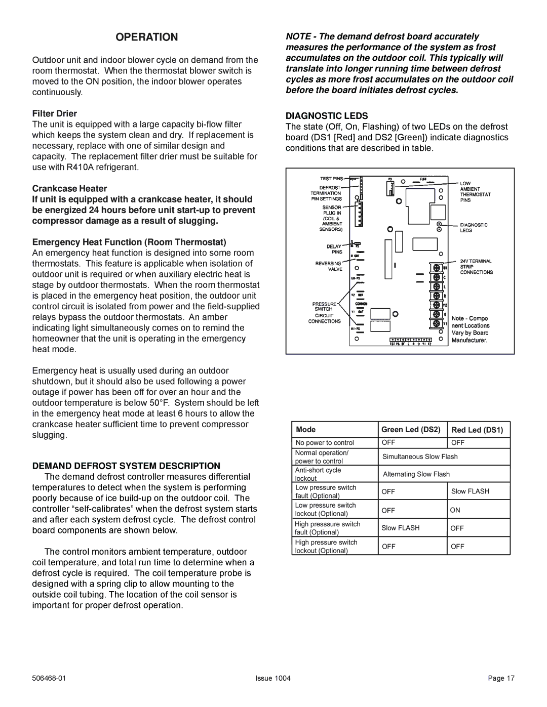
DEMAND DEFROST SYSTEM DESCRIPTION
The demand defrost controller measures differential temperatures to detect when the system is performing poorly because of ice
The control monitors ambient temperature, outdoor coil temperature, and total run time to determine when a defrost cycle is required. The coil temperature probe is designed with a spring clip to allow mounting to the outside coil tubing. The location of the coil sensor is important for proper defrost operation.
NOTE - The demand defrost board accurately measures the performance of the system as frost accumulates on the outdoor coil. This typically will translate into longer running time between defrost cycles as more frost accumulates on the outdoor coil before the board initiates defrost cycles.
DIAGNOSTIC LEDS
The state (Off, On, Flashing) of two LEDs on the defrost board (DS1 [Red] and DS2 [Green]) indicate diagnostics conditions that are described in table.
Mode | Green Led (DS2) | Red Led (DS1) | |
No power to control | OFF | OFF | |
Normal operation/ | Simultaneous Slow Flash | ||
power to control | |||
|
| ||
Alternating Slow Flash |
| ||
lockout |
| ||
|
| ||
Low pressure switch | OFF | Slow FLASH | |
fault (Optional) | |||
|
| ||
Low pressure switch | OFF | ON | |
lockout (Optional) | |||
|
| ||
High presssure switch | Slow FLASH | OFF | |
fault (Optional) | |||
|
| ||
High pressure switch | OFF | OFF | |
lockout (Optional) | |||
|
| ||
Issue 1004 | Page 17 |