Thermostat Demand Wiring
The diagnostic module requires a thermostat demand signal to operate properly. The thermostat demand signal input, labeled Y on the module, should always be con- nected to the compressor contactor coil so that when the coil is energized, the demand signal input is 24VAC. When the coil is not energized, the demand signal input should be less than 0.5VAC.
Miswired Module Codes
Depending on the system configuration, some ALERT flash codes may not be active. The presence of safety switches affects how the system alerts are displayed by the module.
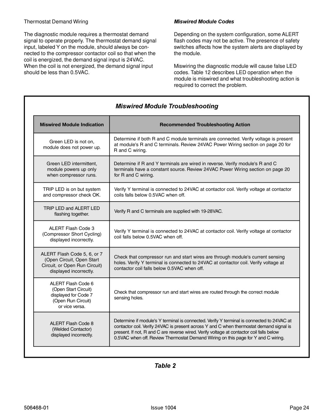
Miswiring the diagnostic module will cause false LED codes. Table 12 describes LED operation when the module is miswired and what troubleshooting action is required to correct the problem.
|
| Miswired Module Troubleshooting | |
|
|
|
|
| Miswired Module Indication | Recommended Troubleshooting Action |
|
|
|
|
|
| Green LED is not on, | Determine if both R and C module terminals are connected. Verify voltage is present |
|
| at module's R and C terminals. Review 24VAC Power Wiring section on page 20 for |
| |
| module does not power up. |
| |
| R and C wiring. |
| |
|
|
| |
|
|
|
|
| Green LED intermittent, | Determine if R and Y terminals are wired in reverse. Verify module's R and C |
|
| module powers up only | terminals have a constant source. Review 24VAC Power Wiring section on page 20 |
|
| when compressor runs. | for R and C wiring. |
|
|
|
|
|
| TRIP LED is on but system | Verify Y terminal is connected to 24VAC at contactor coil. Verify voltage at contactor |
|
| and compressor check OK. | coils falls below 0.5VAC when off. |
|
|
|
|
|
| TRIP LED and ALERT LED | Verify R and C terminals are supplied with |
|
| flashing together. |
| |
|
|
| |
|
|
|
|
| ALERT Flash Code 3 | Verify Y terminal is connected to 24VAC at contactor coil. Verify voltage at contactor |
|
| (Compressor Short Cycling) |
| |
| coil falls below 0.5VAC when off. |
| |
| displayed incorrectly. |
| |
|
|
| |
|
|
|
|
| ALERT Flash Code 5, 6, or 7 | Check that compressor run and start wires are through module's current sensing |
|
| (Open Circuit, Open Start |
| |
| holes. Verify Y terminal is connected to 24VAC at contactor coil. Verify voltage at |
| |
| Circuit, or Open Run Circuit) |
| |
| contactor coil falls below 0.5VAC when off. |
| |
| displayed incorrectly. |
| |
|
|
| |
|
|
|
|
| ALERT Flash Code 6 |
|
|
| (Open Start Circuit) | Check that compressor run and start wires are routed through the correct module |
|
| displayed for Code 7 |
| |
| sensing holes. |
| |
| (Open Run Circuit) |
| |
|
|
| |
| or vice versa. |
|
|
|
|
|
|
| ALERT Flash Code 8 | Determine if module's Y terminal is connected. Verify Y terminal is connected to 24VAC at |
|
| contactor coil. Verify 24VAC is present across Y and C when thermostat demand signal is |
| |
| (Welded Contactor) |
| |
| present. If not, R and C are reverse wired. Verify voltage at contactor coil falls below |
| |
| displayed incorrectly. |
| |
| 0.5VAC when off. Review Thermostat Demand Wiring on this page for Y and C wiring. |
| |
|
|
| |
|
|
|
|
|
|
|
|
|
| Table 12 | |
Issue 1004 | Page 24 |