removed during the first flush. After each system flush, allow the recovery machine to pull a vacuum on the system at the end of the procedure.
9.Close the valve on the inverted R22 cylinder and the gauge set valves. Pump the remaining refrigeraant out of the recovery machine and turn the machine off.
10.Use nitrogen to break the vacuum on the refrigerant lines and indoor coil before removing the recovery machine, gauges, and R22 refrigerant drum.
11.Install a thermal expansion valve approved for use with R410a refrigerant in the liquid line at the indoor coil.
Refrigerant Metering Device
4HP16LT units are designed for use with TXV systems only. An R410a system will not operate properly with an R22 metering device.
Expansion valves equipped with
TXV Data
MODEL | PART NUMBER |
|
|
4HP16LT- 24H4TXV01
4HP16LT - 36H4TXV02
4HP16LT - 48,
Table 3
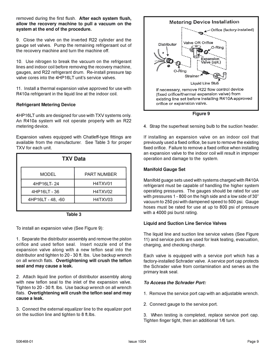
To install an expansion valve (See Figure 9):
1.Separate the distributor assembly and remove the piston orifice and used teflon seal. Insert nozzle end of the expansion valve along with a new teflon seal into the distributor and tighten to 20 - 30 ft. lbs. Use backup wrench on all wrench flats. Overtightening will crush the teflon seal and may cause a leak.
2.Attach liquid line portion of distributor assembly along with new teflon seal to the inlet of the expansion valve. Tighten to 20 - 30 ft. lbs. Use backup wrench on all wrench flats. Overtightening will crush the teflon seal and may cause a leak.
3.Connect the external equalizer line to the equalizer port on the suction line and tighten to 8 ft.lbs.
Figure 9
4. Strap the superheat sensing bulb to the suction header.
If installing an expansion valve on an indoor coil that previously used a fixed orifice, be sure to remove the existing fixed orifice. Failure to remove a fixed orifice when installing an expansion valve to the indoor coil will result in improper operation and damage to the system.
Manifold Gauge Set
Manifold guage sets used with systems charged with R410A refrigerant must be capable of handling the higher system operating pressures. The gauges should be rated for use with pressures 1 - 800 on the high side and a low side of 30” vacuum to 250 psi with dampened speed to 500 psi. Gauge hoses must be rated for use at up to 800 psi of pressure with a 4000 psi burst rating.
Liquid and Suction Line Service Valves
The liquid line and suction line service valves (See Figure
11)and service ports are used for leak teating, evacuation, charging, and checking charge.
Each valve is equipped with a service port which has a
To Access the Schrader Port:
1.Remove the service port cap with an adjustable wrench.
2.Connect gauge to the service port.
3.When testing is completed, replace service port cap. Tighten finger tight, then an additional 1/6 turn.
Issue 1004 | Page 9 |