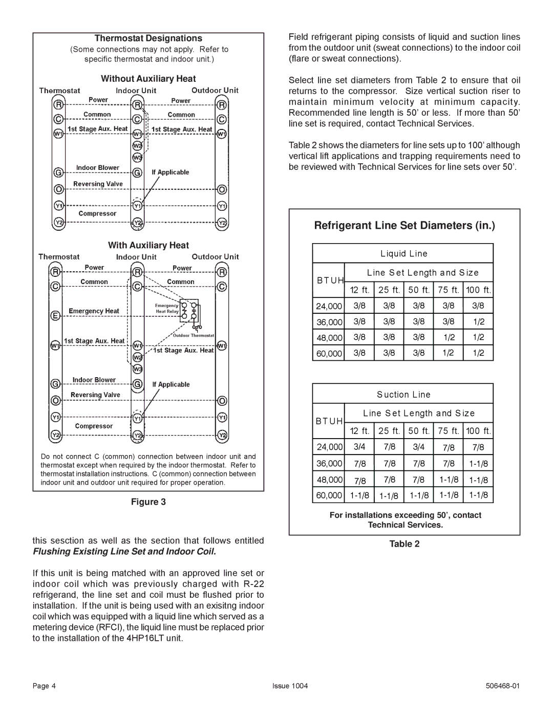
Thermostat Designations
(Some connections may not apply. Refer to
specific thermostat and indoor unit.)
Without Auxiliary Heat
Field refrigerant piping consists of liquid and suction lines from the outdoor unit (sweat connections) to the indoor coil (flare or sweat connections).
Select line set diameters from Table 2 to ensure that oil returns to the compressor. Size vertical suction riser to maintain minimum velocity at minimum capacity. Recommended line length is 50’ or less. If more than 50’ line set is required, contact Technical Services.
Table 2 shows the diameters for line sets up to 100’ although vertical lift applications and trapping requirements need to be reviewed with Technical Services for line sets over 50’.
Refrigerant Line Set Diameters (in.)
With Auxiliary Heat
B T UH
Liquid Line
Line S et Length and S ize
12 ft. 25 ft. 50 ft. 75 ft. 100 ft.
24,000 3/8 3/8 3/8 3/8 3/8
36,000 3/8 3/8 3/8 3/8 1/2
48,000 3/8 3/8 3/8 1/2 1/2
60,000 3/8 3/8 3/8 1/2 1/2
B T UH
S uction Line
Line S et Length and S ize
Do not connect C (common) connection between indoor unit and thermostat except when required by the indoor thermostat. Refer to thermostat installation instructions. C (common) connection between indoor unit and outdoor unit required for proper operation.
Figure 3
this sesction as well as the section that follows entitled
Flushing Existing Line Set and Indoor Coil.
If this unit is being matched with an approved line set or indoor coil which was previously charged with
12 ft. 25 ft. 50 ft. 75 ft. 100 ft. 24,000 3/4 7/8 3/4 7/8 7/8
36,000 7/8 7/8 7/8 7/8
48,000 7/8 7/8 7/8
60,000
For installations exceeding 50’, contact
Technical Services.
Table 2
Page 4 | Issue 1004 |
