![]()
![]() WARNING
WARNING
Polyol ester (POE) oils used with R410A refrigerant absorb moisture very quickly. It is very important that the refrigerant system be kept closed as much as possible. DO NOT remove line set caps or service valve stub caps until ready to make connections.
Installing Refrigerant Line
During the installation of an air conditioning system, it is important to properly isolate the refrigerant line to prevent unnecessary vibration. Line set contact with the structure (wall, ceiling, or floor) may cause objectionable noise when vibration is translated into sound. As a result, more energy or vibration can be expected. Close attention to line set isolation must be observed.
Following are some points to consider when placing and installing a
Placement
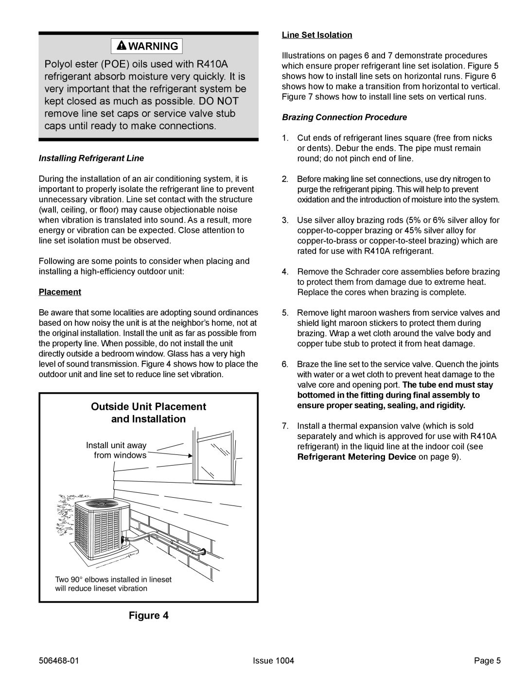
Be aware that some localities are adopting sound ordinances based on how noisy the unit is at the neighbor’s home, not at the original installation. Install the unit as far as possible from the property line. When possible, do not install the unit directly outside a bedroom window. Glass has a very high level of sound transmission. Figure 4 shows how to place the outdoor unit and line set to reduce line set vibration.
Outside Unit Placement
and Installation
Install unit away from windows
Two 90° elbows installed in lineset will reduce lineset vibration
Figure 4
Line Set Isolation
Illustrations on pages 6 and 7 demonstrate procedures which ensure proper refrigerant line set isolation. Figure 5 shows how to install line sets on horizontal runs. Figure 6 shows how to make a transition from horizontal to vertical. Figure 7 shows how to install line sets on vertical runs.
Brazing Connection Procedure
1.Cut ends of refrigerant lines square (free from nicks or dents). Debur the ends. The pipe must remain round; do not pinch end of line.
2.Before making line set connections, use dry nitrogen to purge the refrigerant piping. This will help to prevent oxidation and the introduction of moisture into the system.
3.Use silver alloy brazing rods (5% or 6% silver alloy for
4.Remove the Schrader core assemblies before brazing to protect them from damage due to extreme heat. Replace the cores when brazing is complete.
5.Remove light maroon washers from service valves and shield light maroon stickers to protect them during brazing. Wrap a wet cloth around the valve body and copper tube stub to protect it from heat damage.
6.Braze the line set to the service valve. Quench the joints with water or a wet cloth to prevent heat damage to the valve core and opening port. The tube end must stay bottomed in the fitting during final assembly to ensure proper seating, sealing, and rigidity.
7.Install a thermal expansion valve (which is sold separately and which is approved for use with R410A refrigerant) in the liquid line at the indoor coil (see
Refrigerant Metering Device on page 9).
Issue 1004 | Page 5 |