24POE | Figure 3 |
| ||||||||||||
| ||||||||||||||
|
|
|
|
|
| SFP Ports | Power Diagnostic | |||||||
|
|
| LED LED | |||||||||||
|
|
|
|
|
|
|
|
|
|
|
|
|
|
|
|
|
|
|
|
|
|
|
|
|
|
|
|
|
|
|
|
|
|
|
|
|
|
|
|
|
|
|
|
|
|
|
|
|
|
|
|
|
|
|
|
|
|
|
|
|
|
|
|
|
|
|
|
|
|
|
|
|
|
|
|
|
|
|
|
|
|
|
|
|
|
|
|
|
|
|
|
|
|
|
|
|
|
|
|
|
|
|
|
|
|
|
|
|
|
|
|
|
|
|
|
|
|
|
|
|
|
|
|
|
|
|
|
|
|
|
|
|
|
|
Stacking
LEDs
The
1337
24 10/100/1000Mbps ports —
4 SFP Ports — There are four
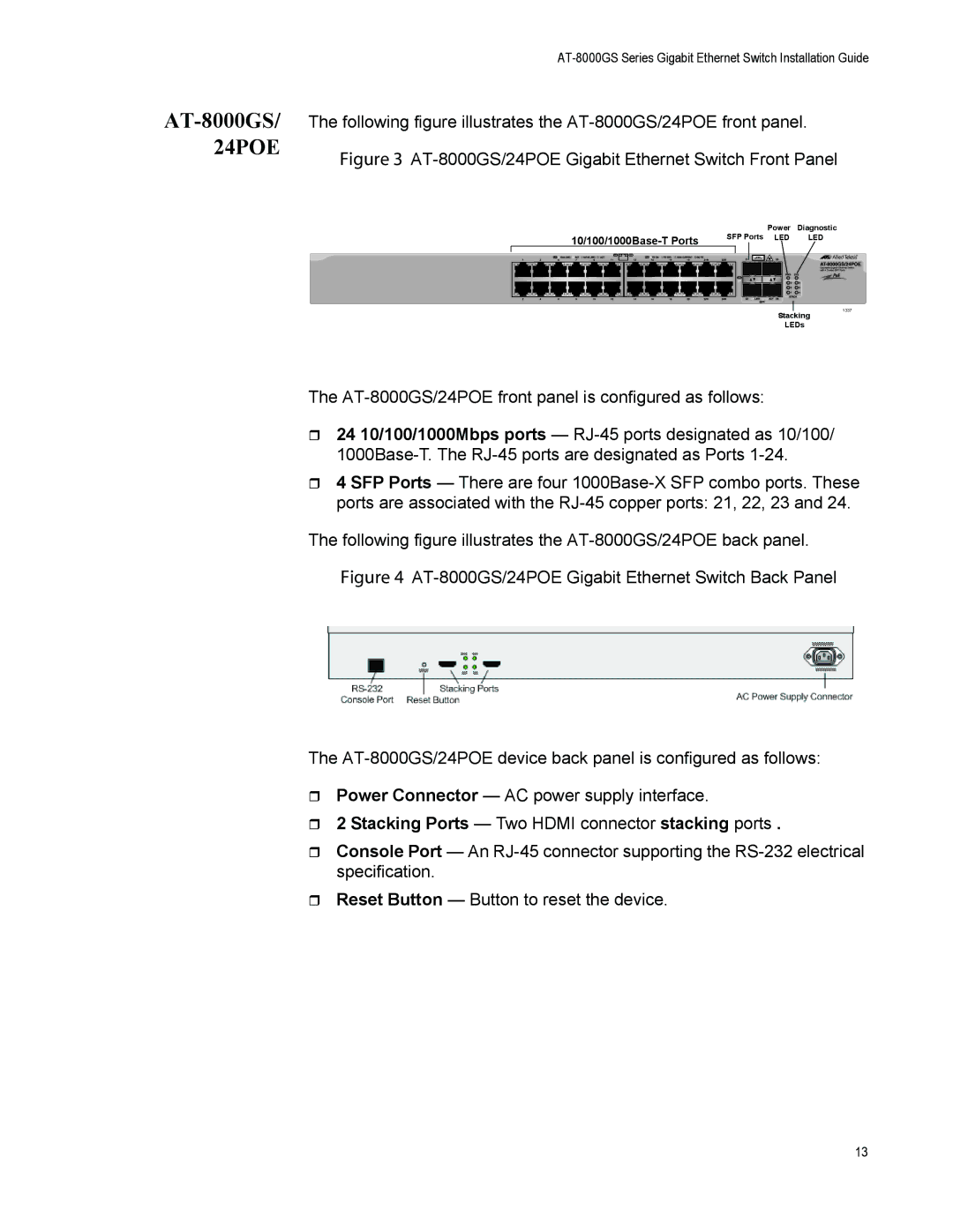
The following figure illustrates the
Figure 4 AT-8000GS/24POE Gigabit Ethernet Switch Back Panel
The AT-8000GS/24POE device back panel is configured as follows:
Power Connector — AC power supply interface.
2 Stacking Ports — Two HDMI connector stacking ports .
Console Port — An
Reset Button — Button to reset the device.
13