Chapter 1: Overview
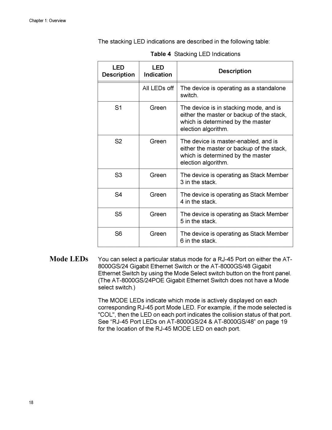
The stacking LED indications are described in the following table:
Table 4 Stacking LED Indications
LED | LED | Description | |
Description | Indication | ||
| |||
|
|
| |
|
|
| |
| All LEDs off | The device is operating as a standalone | |
|
| switch. | |
|
|
| |
S1 | Green | The device is in stacking mode, and is | |
|
| either the master or backup of the stack, | |
|
| which is determined by the master | |
|
| election algorithm. | |
|
|
| |
S2 | Green | The device is | |
|
| either the master or backup of the stack, | |
|
| which is determined by the master | |
|
| election algorithm. | |
|
|
| |
S3 | Green | The device is operating as Stack Member | |
|
| 3 in the stack. | |
|
|
| |
S4 | Green | The device is operating as Stack Member | |
|
| 4 in the stack. | |
|
|
| |
S5 | Green | The device is operating as Stack Member | |
|
| 5 in the stack. | |
|
|
| |
S6 | Green | The device is operating as Stack Member | |
|
| 6 in the stack. | |
|
|
|
Mode LEDs You can select a particular status mode for a
The MODE LEDs indicate which mode is actively displayed on each corresponding
18