RJ-45 Port LEDs on AT-8000GS/24 & AT-8000GS/48
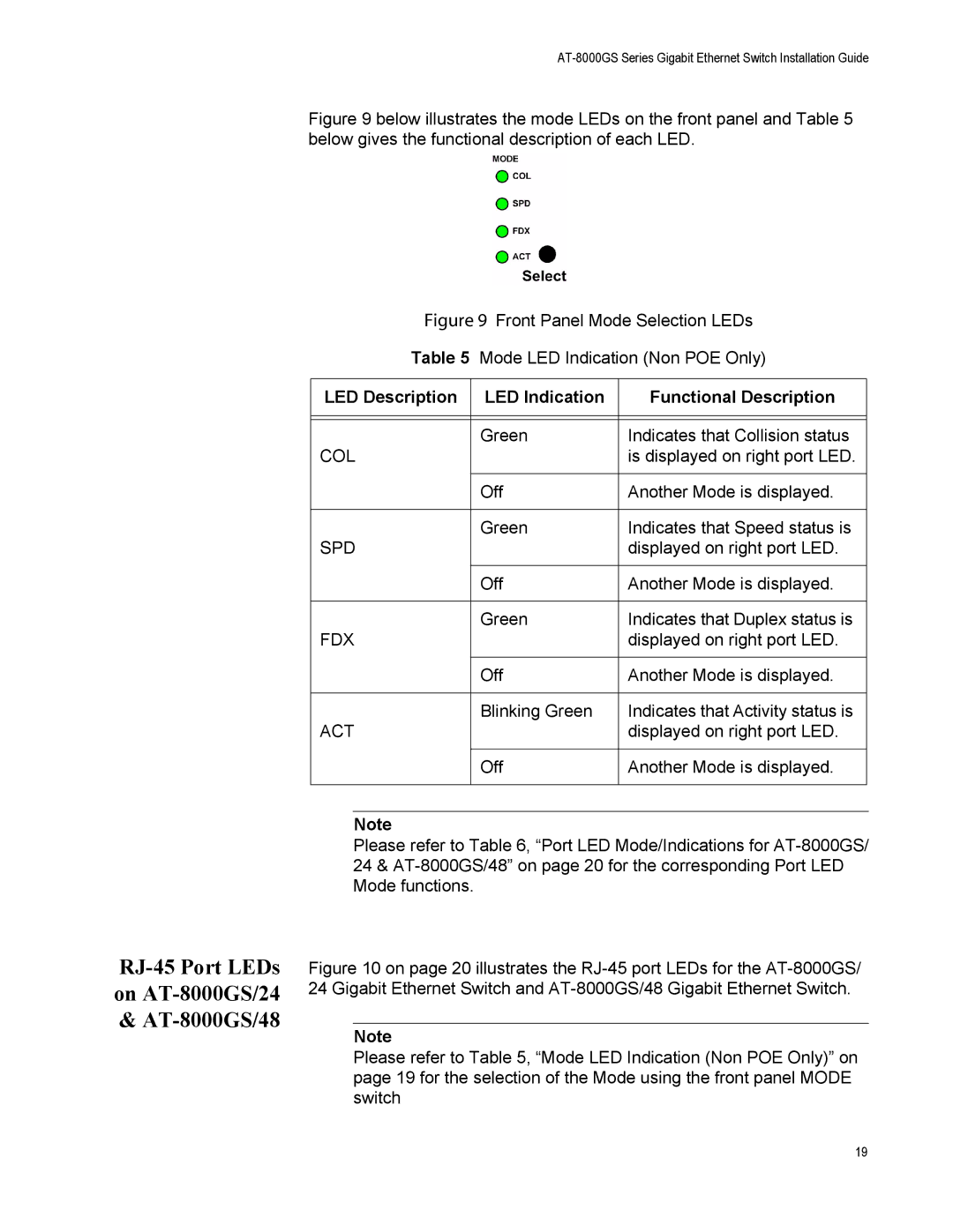
Figure 9 below illustrates the mode LEDs on the front panel and Table 5 below gives the functional description of each LED.
Figure 9 Front Panel Mode Selection LEDs
Table 5 Mode LED Indication (Non POE Only)
LED Description | LED Indication | Functional Description |
|
|
|
|
|
|
| Green | Indicates that Collision status |
COL |
| is displayed on right port LED. |
|
|
|
| Off | Another Mode is displayed. |
|
|
|
| Green | Indicates that Speed status is |
SPD |
| displayed on right port LED. |
|
|
|
| Off | Another Mode is displayed. |
|
|
|
| Green | Indicates that Duplex status is |
FDX |
| displayed on right port LED. |
|
|
|
| Off | Another Mode is displayed. |
|
|
|
| Blinking Green | Indicates that Activity status is |
ACT |
| displayed on right port LED. |
|
|
|
| Off | Another Mode is displayed. |
|
|
|
Note
Please refer to Table 6, “Port LED Mode/Indications for
Figure 10 on page 20 illustrates the RJ-45 port LEDs for the AT-8000GS/ 24 Gigabit Ethernet Switch and AT-8000GS/48 Gigabit Ethernet Switch.
Note
Please refer to Table 5, “Mode LED Indication (Non POE Only)” on page 19 for the selection of the Mode using the front panel MODE switch
19