Allied Telesis AT-8000GS/POE, AT-8000GS/24 manual Attaching the Mounting Brackets

Models: AT-8000GS/POE AT-8000GS/24

1 52
Download 52 pages 28.09 Kb
Page 33
Image 33

AT-8000GS Series Gigabit Ethernet Switch Installation Guide

Disconnect all cables from the unit before mounting the device in a rack or cabinet.

When mounting multiple devices into a rack, mount the devices from the bottom up.

To install the device in a rack, perform the following:

1.It is recommended to put on an ESD wrist strap and attach the ESD clip to a metal surface to act as ground. An ESD strap is not supplied with the device.

2.Place the device on a flat and stable surface.

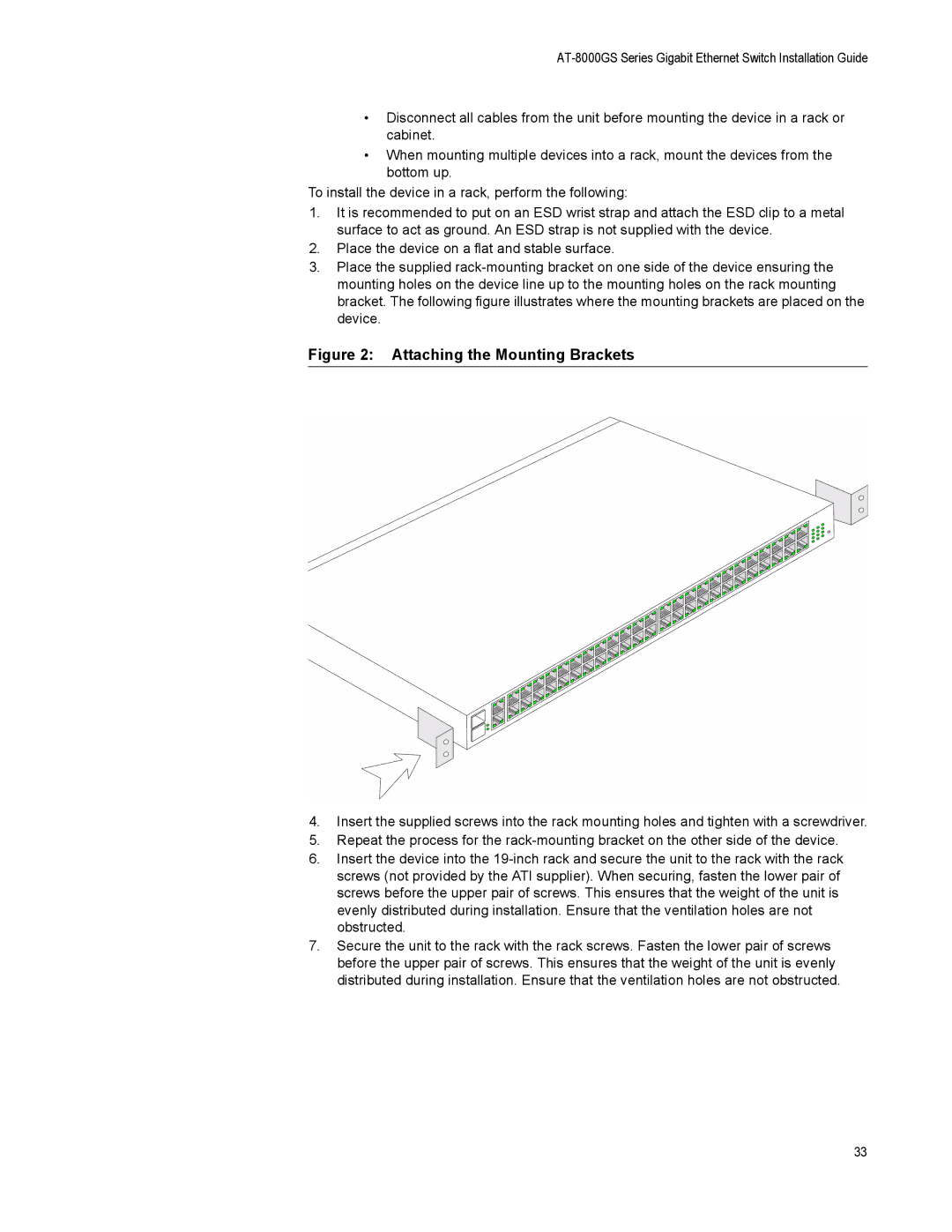
3.Place the supplied rack-mounting bracket on one side of the device ensuring the mounting holes on the device line up to the mounting holes on the rack mounting bracket. The following figure illustrates where the mounting brackets are placed on the device.

Figure 2: Attaching the Mounting Brackets

4.Insert the supplied screws into the rack mounting holes and tighten with a screwdriver.

5.Repeat the process for the rack-mounting bracket on the other side of the device.

6.Insert the device into the 19-inch rack and secure the unit to the rack with the rack screws (not provided by the ATI supplier). When securing, fasten the lower pair of screws before the upper pair of screws. This ensures that the weight of the unit is evenly distributed during installation. Ensure that the ventilation holes are not obstructed.

7.Secure the unit to the rack with the rack screws. Fasten the lower pair of screws before the upper pair of screws. This ensures that the weight of the unit is evenly distributed during installation. Ensure that the ventilation holes are not obstructed.

33

Page 33
Image 33
Allied Telesis AT-8000GS/POE, AT-8000GS/24 manual Attaching the Mounting Brackets