Chapter 2: Virtual Chassis Stacking

Ring Configuration

100-240VAC~

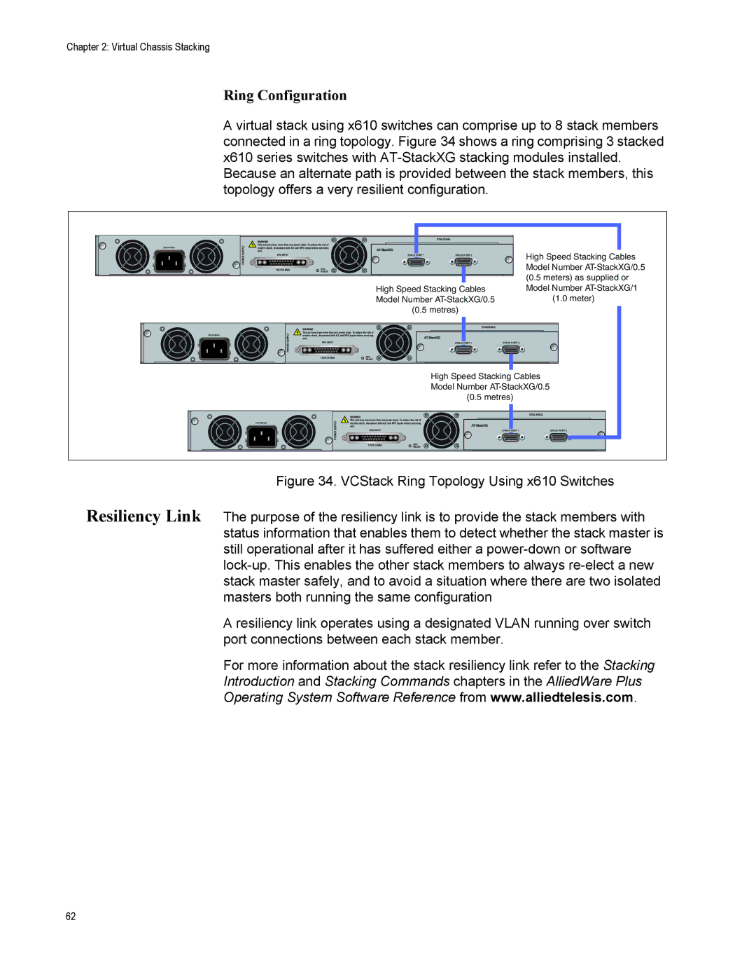
A virtual stack using x610 switches can comprise up to 8 stack members connected in a ring topology. Figure 34 shows a ring comprising 3 stacked x610 series switches with AT-StackXG stacking modules installed.

Because an alternate path is provided between the stack members, this topology offers a very resilient configuration.


WARNING


STACKING


SUPPLY

This unit may have more than one power input. To reduce the risk of


electric shock, disconnect both A/C and RPS inputs before servicing

AT-StackXG


unit.


High Speed Stacking Cables


POWER

RPS INPUT


STACK PORT 1

STACK PORT 2


Model Number AT-StackXG/0.5


12V/21A MAX

READY


RPS


(0.5 meters) as supplied or


High Speed Stacking Cables


Model Number AT-StackXG/1


Model Number AT-StackXG/0.5


(1.0 meter)


(0.5 metres)


WARNING


STACKING


SUPPLY

This unit may have more than one power input. To reduce the risk of


100-240VAC~


electric shock, disconnect both A/C and RPS inputs before servicing

AT-StackXG


unit.


POWER

RPS INPUT


STACK PORT 1

STACK PORT 2


12V/21A MAX

RPS


READY


High Speed Stacking Cables


Model Number AT-StackXG/0.5


(0.5 metres)


WARNING


STACKING


SUPPLY

This unit may have more than one power input. To reduce the risk of


100-240VAC~

electric shock, disconnect both A/C and RPS inputs before servicing

AT-StackXG


unit.


POWER

RPS INPUT


STACK PORT 1

STACK PORT 2


12V/21A MAX

RPS


READY


Figure 34. VCStack Ring Topology Using x610 Switches

Resiliency Link The purpose of the resiliency link is to provide the stack members with status information that enables them to detect whether the stack master is still operational after it has suffered either a power-down or software lock-up. This enables the other stack members to always re-elect a new stack master safely, and to avoid a situation where there are two isolated masters both running the same configuration

A resiliency link operates using a designated VLAN running over switch port connections between each stack member.

For more information about the stack resiliency link refer to the Stacking

Introduction and Stacking Commands chapters in the AlliedWare Plus

Operating System Software Reference from www.alliedtelesis.com.

62

Page 62
Image 62
Allied Telesis X610-48TS/X-POE+, X610-48TS-POE+, X610-24TS-POE+, X610-24SPS/X, X610-24TS/X-POE+ manual Ring Configuration

X610-48TS/X-POE+, X610-48TS, X610-24TS/X, X610-24TS/X-POE+, X610-24SPS/X specifications

Allied Telesis has made a significant mark in the networking hardware industry with its impressive lineup of switching solutions. Among these, the X610 series stands out, offering a range of models including the X610-48TS, X610-24TS/X-POE+, X610-24TS/X, X610-48TS-POE+, and X610-24TS-POE+. These switches are designed for robust performance, scalability, and energy efficiency, catering to the needs of businesses and organizations of various sizes.

The X610-48TS model features 48 Gigabit Ethernet ports, providing high-density connectivity options that are essential for modern network architectures. Complementing this, the X610-24TS models, which come with 24 ports, are ideal for smaller deployments while still delivering significant capacity and performance. The X610-24TS/X-POE+ variant enhances this capability further by incorporating Power over Ethernet, enabling the switch to deliver both data and power over the same cable. This feature simplifies installations of IP-based devices such as cameras, phones, and wireless access points.

All models in the X610 series support advanced Layer 2 and Layer 3 features, enabling efficient network management and control. With support for VLANs, Spanning Tree Protocol, and link aggregation, these switches facilitate better traffic management and redundancy, crucial for maintaining high availability in enterprise environments. Additionally, the ability to implement Quality of Service (QoS) ensures that critical applications receive the bandwidth necessary for optimum performance.

Energy efficiency is a hallmark of Allied Telesis products, and the X610 series is no exception. The switches incorporate technologies like Energy Efficient Ethernet (EEE), which helps reduce power consumption during periods of low network activity, thus lowering operational costs while supporting eco-friendly initiatives.

Security features are also robust, with mechanisms such as access control lists (ACLs), port security, and built-in DHCP snooping ensuring that the network remains secure against unauthorized access and threats. The switches are designed with a user-friendly interface for easy configuration and management, including support for SNMP and a web-based management interface.

In conclusion, Allied Telesis' X610 series, with its various models, offers an impressive blend of performance, scalability, and energy efficiency. These switches are well-suited for a wide variety of applications, making them an ideal choice for organizations looking to upgrade or establish a reliable networking infrastructure. Their advanced features, coupled with a focus on security and management, provide organizations with the tools necessary to handle current and future networking demands.