AT-9924SP-30, AT-9924T-40, AT-8948, AT-9924T/4SP-A-20, X900-48FE-N specifications
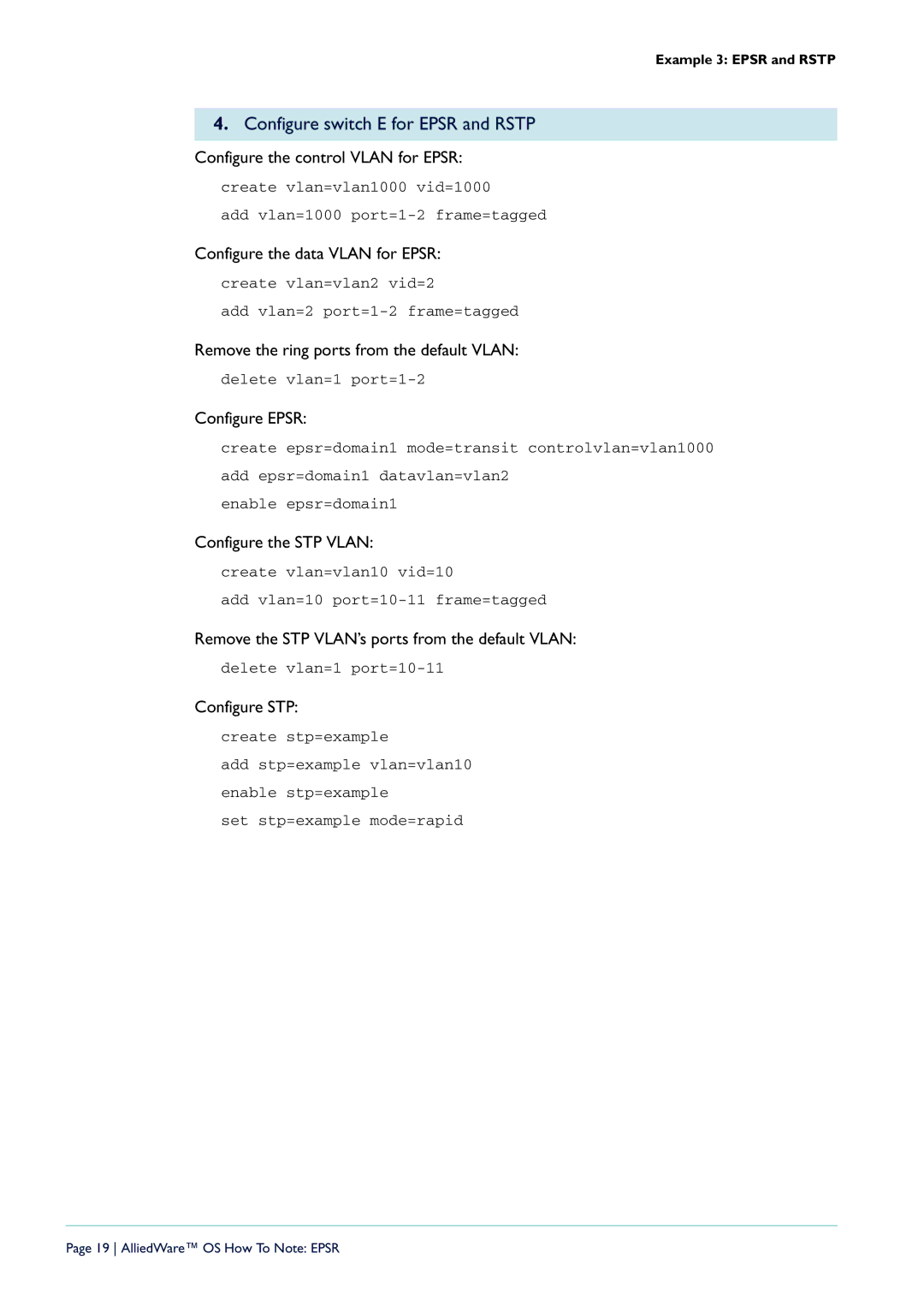
Allied Telesis is a leading provider of networking solutions, renowned for its innovative technologies and high-performance networking equipment. Among its extensive product lineup, the X900-48FE-N, AT-9924T-40, AT-8948, AT-9924T/4SP-A-20, and AT-9924SP-30 stand out for their remarkable features and capabilities.The X900-48FE-N is a robust layer 2/3 managed switch that features 48 Fast Ethernet ports. This model is particularly known for its energy efficiency and reliability, making it a suitable choice for enterprises with demanding networking needs. It supports a wide range of Layer 2 Ethernet switching technologies, including VLANs, Spanning Tree Protocol (STP), and Link Aggregation Control Protocol (LACP), which enhances network reliability and efficiency.
The AT-9924T-40 is a versatile switch designed for high-performance environments. It offers a rich set of features, including 24 Gigabit Ethernet ports and 4 SFP ports for fiber connectivity. This device is equipped with Advanced Layer 2 and Layer 3 features, including IPv4/IPv6 support, Quality of Service (QoS) capabilities, and robust security options. This switch is ideal for core and distribution deployments within enterprise networks, ensuring fast and reliable connectivity.
The AT-8948 is another important model in Allied Telesis' offerings. It features 48 10/100 Mbps Ethernet ports and 4 Gigabit uplink ports, providing a high density of connectivity options. The AT-8948 is also equipped with advanced management capabilities, including SNMP, RMON, and web-based management, allowing for easy configuration and monitoring of the network.
The AT-9924T/4SP-A-20 offers a combination of 24 Gigabit Ethernet ports and 4 SFP slots to extend network capabilities through fiber connections. It is particularly well-suited for environments requiring high bandwidth and flexible connectivity. Its compact design makes it an excellent choice for data centers and enterprise networks.
Lastly, the AT-9924SP-30 is characterized by its 24 Gigabit SFP ports, offering flexibility in terms of fiber connectivity. This switch supports advanced routing capabilities and is designed for high-availability environments. Its ability to handle diverse network traffic while maintaining optimal performance makes it a valuable asset for any modern enterprise.
In summary, these Allied Telesis models showcase advanced features, network reliability, and versatile management options, making them critical components for efficient and scalable networking solutions.

