
CDA-7998 specifications
The Alpine CDA-7998 is a high-performance car audio receiver renowned for its advanced features and superior sound quality. Designed for audiophiles and car enthusiasts alike, this model combines cutting-edge technology with a user-friendly interface to enhance the in-car listening experience.One of the standout features of the CDA-7998 is its exceptional audio quality. The receiver is equipped with a 24-bit digital-to-analog converter (DAC), which processes sound with unparalleled precision, reducing distortion and increasing clarity. This technology allows users to enjoy their favorite music with exceptional accuracy, making every note and tone come alive.
Another remarkable aspect of the CDA-7998 is its versatile connectivity options. The unit includes a front USB input, enabling easy connection to various devices, such as flash drives or smartphones. Additionally, it incorporates a 3.5 mm auxiliary input for added flexibility, allowing users to connect external devices with ease. The receiver supports playback of various audio formats, including MP3, WMA, and AAC, providing users with a vast library of music to choose from.
The CDA-7998 also features Bluetooth technology, which allows for hands-free calling and wireless audio streaming. This is particularly beneficial for maintaining focus on the road while enjoying a seamless connection to mobile devices. The built-in microphone ensures clear communication during calls, while the audio streaming feature allows users to enjoy their playlist without the hassle of cables.
Customization is a key aspect of the CDA-7998. The receiver includes a 3-band parametric equalizer, enabling users to adjust bass, midrange, and treble frequencies according to their preferences. Additionally, with its customizable color display and button illumination, users can personalize the aesthetic of their car’s interior, enhancing the overall experience.
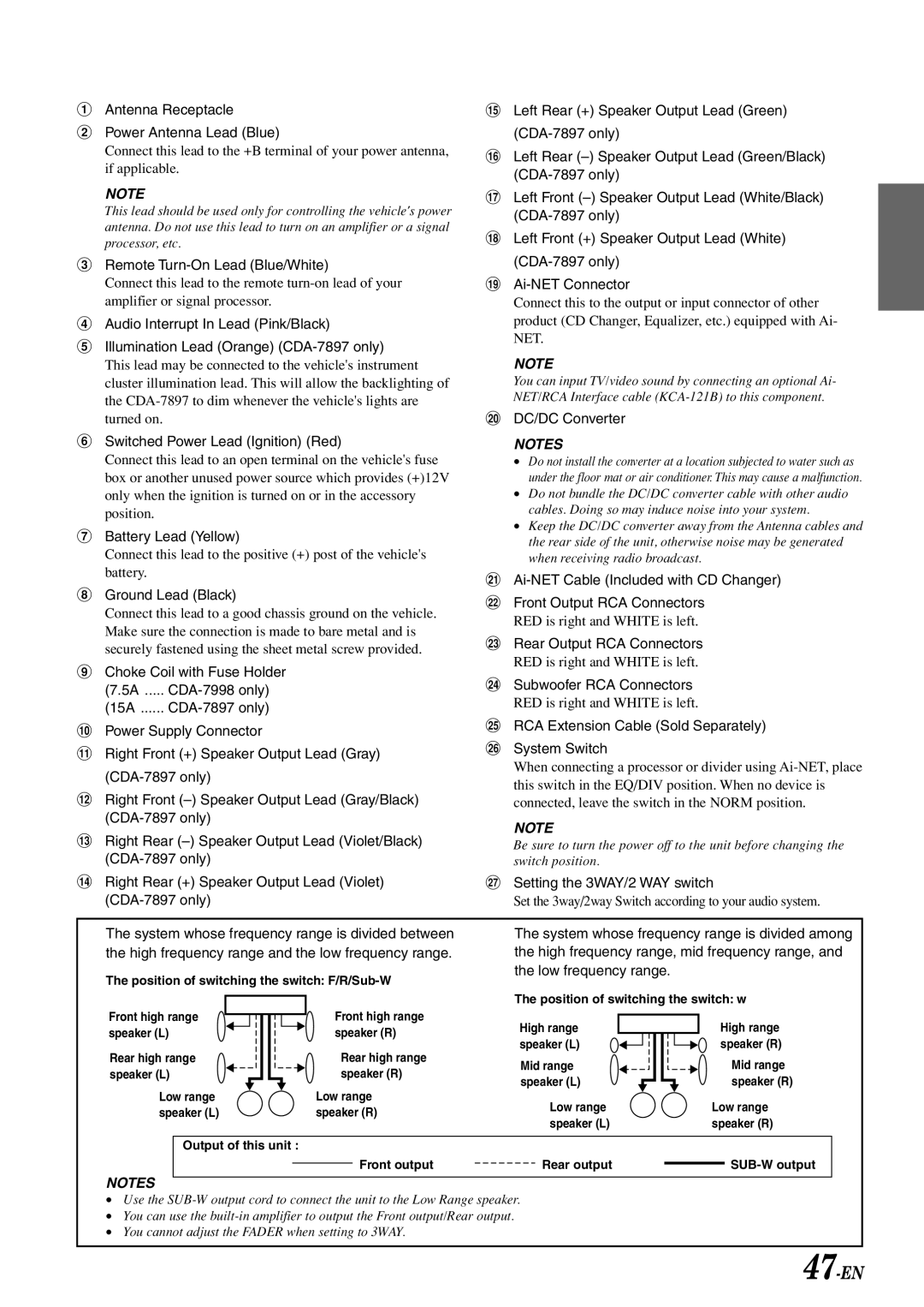
Furthermore, the CDA-7998 supports additional amplification with its dedicated line outputs for front, rear, and subwoofer channels. This allows for a multi-channel audio setup, delivering an immersive sound experience that can satisfy even the most discerning listeners.
Overall, the Alpine CDA-7998 is a sophisticated car audio receiver that combines advanced technology with unparalleled sound quality and customization options, making it an ideal choice for anyone looking to elevate their in-car audio experience.