IVA-D300 specifications
The Alpine IVA-D300 is a sophisticated in-car audio and video system that epitomizes cutting-edge technology in the realm of automotive entertainment. Designed to elevate the in-car experience, the IVA-D300 combines reliable performance with a sleek interface, making it a popular choice among car enthusiasts and casual users alike.One of the standout features of the IVA-D300 is its 7-inch motorized touchscreen display. This high-resolution screen ensures clear visuals, whether you're watching movies or navigating through your music library. The touchscreen interface is intuitive, allowing users to easily access their favorite media and settings.
The IVA-D300 supports a wide range of audio and video formats, ensuring compatibility with a variety of devices. With options for DVD playback, CD playback, and even MP3/WMA file support, this unit accommodates nearly all your entertainment needs. Furthermore, it boasts the capability to connect to external devices through USB and auxiliary inputs. This feature allows users to effortlessly link their smartphones or portable music players, enhancing the versatility of the system.
In terms of audio performance, the IVA-D300 offers a powerful 4-channel amplifier with adjustable sound settings. Users can fine-tune their audio experience with a built-in equalizer and various sound enhancement technologies. The inclusion of a built-in crossover also allows for optimal speaker performance by directing specific frequencies to the appropriate speakers.
A noteworthy technological advancement in the IVA-D300 is its support for Bluetooth connectivity. This feature not only enables hands-free calling but also allows for wireless audio streaming from smartphones and other compatible devices. The integration of Bluetooth technology emphasizes convenience and enhances safety, as drivers can focus on the road while staying connected.
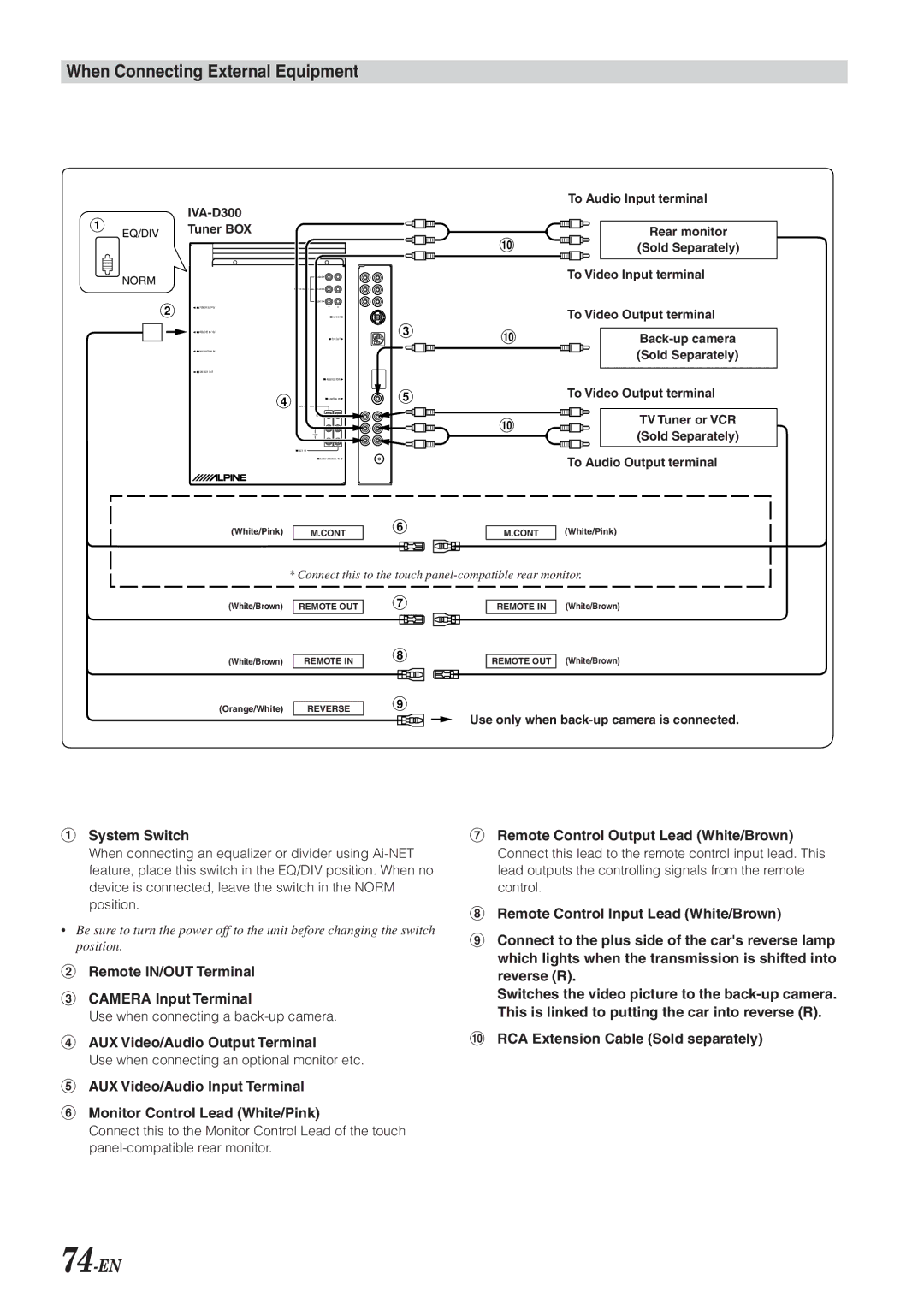
Moreover, the IVA-D300 is designed with expanding capabilities in mind. The system can be integrated with various accessories such as satellite radio and rearview cameras, providing users with a more comprehensive multimedia experience.
In summary, the Alpine IVA-D300 is a feature-rich in-car entertainment system that stands out for its advanced technologies and user-friendly design. Its high-quality display, extensive media compatibility, powerful audio features, and Bluetooth connectivity make it an excellent choice for anyone looking to enhance their in-car experience. With the IVA-D300, drivers can enjoy both the journey and their favorite entertainment seamlessly.

