MATRIX SWITCHERS
INSTALLING YOUR SWITCHER | 6 |
Step 1. Connect the power entry connector of the MAX Switcher to the power outlet with the provided power cord. The power supply is universal and will work throughout the world with voltages between
Step 2. Connect the cables from the video sources (computers, VCR, others) to available inputs 1 through 8 and connect the display device (i.e. monitor or projector) to available outputs 1 through 4.
CAUTION:
All video inputs to MAX Series are DC coupled for best performance. Even though the video inputs are fully isolated, verify with an electrician that all of the grounding is proper and that GROUND LOOP problems are minimized. Severe Ground loop type conditions can damage equipment.
MAXIMUM VIDEO INPUT:
MAXIMUM AUDIO/SYNC INPUT: +/- 5 VOLTS
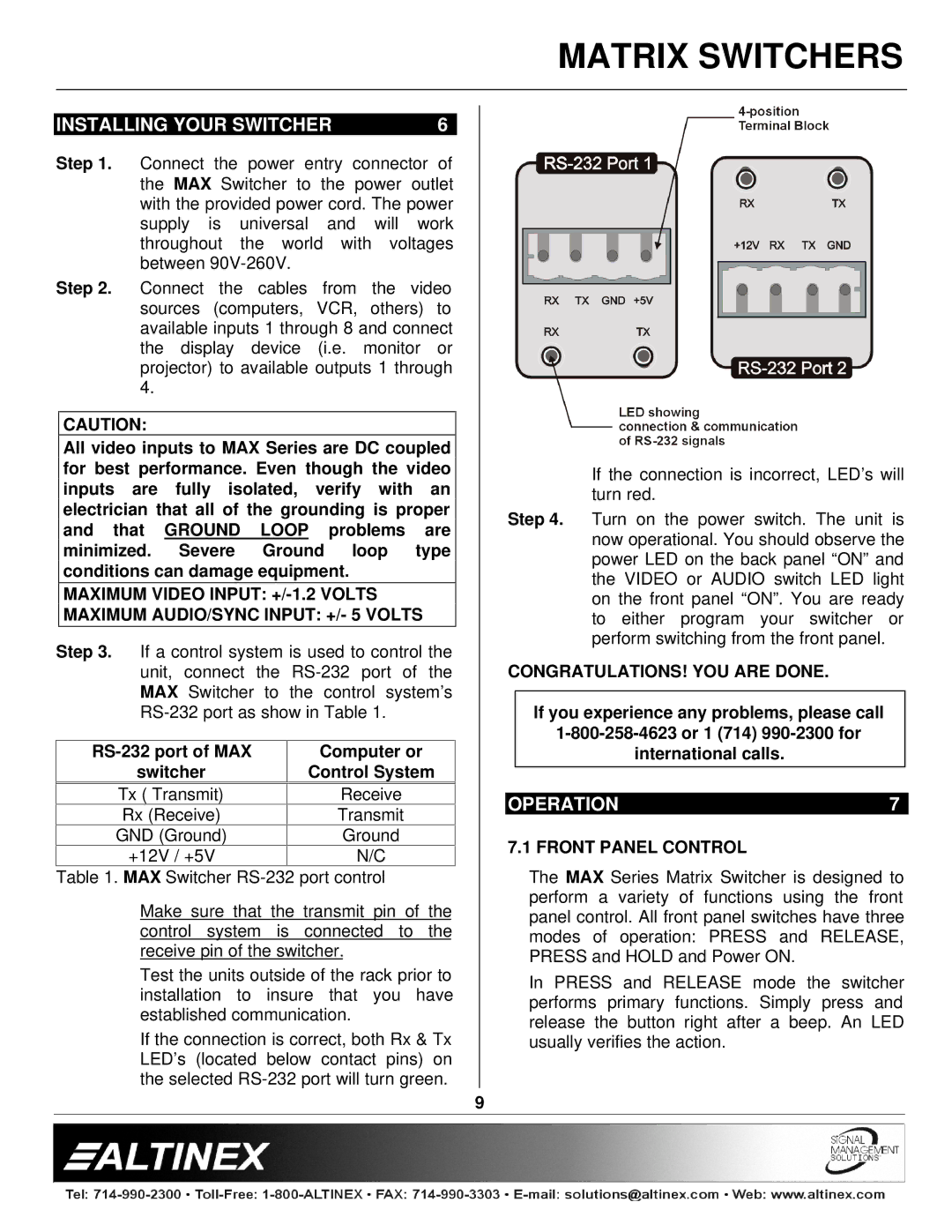
Step 3. If a control system is used to control the unit, connect the
Computer or | |
switcher | Control System |
|
|
Tx ( Transmit) | Receive |
Rx (Receive) | Transmit |
GND (Ground) | Ground |
+12V / +5V | N/C |
Table 1. MAX Switcher
Make sure that the transmit pin of the control system is connected to the receive pin of the switcher.
Test the units outside of the rack prior to installation to insure that you have established communication.
If the connection is correct, both Rx & Tx LED’s (located below contact pins) on the selected
If the connection is incorrect, LED’s will turn red.
Step 4. Turn on the power switch. The unit is now operational. You should observe the power LED on the back panel “ON” and the VIDEO or AUDIO switch LED light on the front panel “ON”. You are ready to either program your switcher or perform switching from the front panel.
CONGRATULATIONS! YOU ARE DONE.
If you experience any problems, please call
international calls.
OPERATION | 7 |
7.1 FRONT PANEL CONTROL
The MAX Series Matrix Switcher is designed to perform a variety of functions using the front panel control. All front panel switches have three modes of operation: PRESS and RELEASE, PRESS and HOLD and Power ON.
In PRESS and RELEASE mode the switcher performs primary functions. Simply press and release the button right after a beep. An LED usually verifies the action.
9