Manuals
/
Altinex
/
Computer Equipment
/
Switch
Altinex
MT105-120/121
manual
Diagram 1 Typical Setup
Models:
MT105-120/121
1
6
23
23
Download
23 pages
56.69 Kb
3
4
5
6
7
8
9
10
Install
Diagram 1 Typical Setup
Warranty
Reset Card to Factory Default
Description of Commands
Using Menu Mode
Menu Mode Examples
Page 6
Image 6
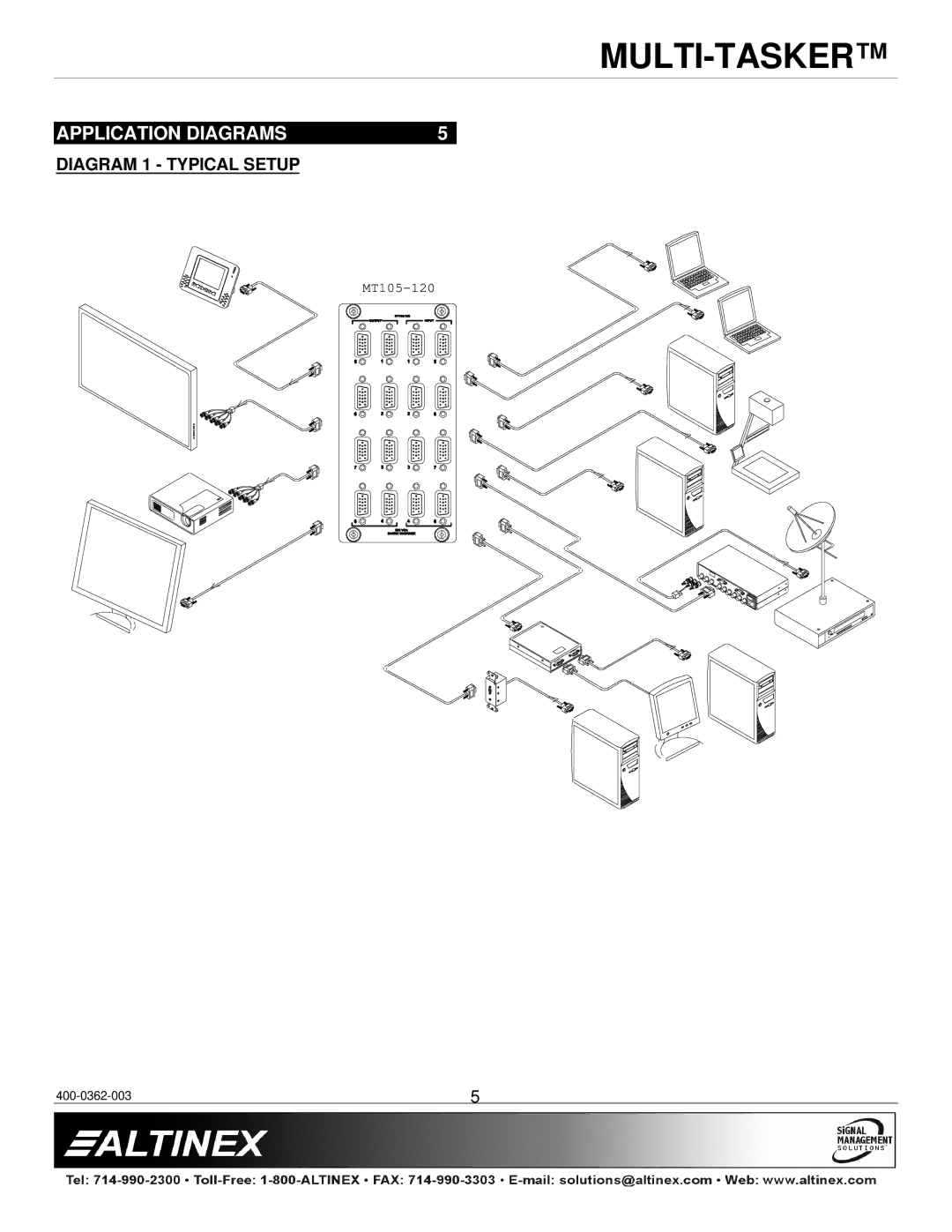
MULTI-TASKER™
APPLICATION DIAGRAMS
5
DIAGRAM 1 - TYPICAL SETUP
MT105-120
400-0362-003
5
Page 5
Page 7
Page 6
Image 6
Page 5
Page 7
Contents
MT105-120/121
Table of Contents
General
Installation
Cleaning
MT105-120/121
About Your MULTI-TASKER Technical Specifications
MT105-120 Front Panel
Diagram 1 Typical Setup
Diagram 2 MT105-120 Internal View
Diagram 3 MT105-121 Internal View
Description of Commands
RS-232 Control
1 RS-232 Interface
VER
CnS
?CnUi
STA
+MA
+ON
Sigi
SDL
SDLm=s
Sigo
Path Operation
10. on
Single Card Operation
Feedback Operation
OFF
Group Operation
OFF1C6P OFF3C7P
14. …P Path
16. IO
CLR
Help
MATmXnCi
Test
21. WR
RMC
RMG
24. RD
Clrg
CLM
G1=EMPTY
Menu Mode
Menu Command Definitions
Using Menu Mode
Menu Types
4 MT105-120/121 Menus
Switch IN-OUT Enter a Number
Save this SETTING?
Reset Card to Factory Default
ESC GO Back KEY= SET Matrix Config
Connect Input 2 to Output
Menu Mode Examples
Set Sync Delay for Output 1 to 2 seconds
Turn OFF Output
Limited WARRANTY/RETURN Policy
Card is not Recognized
No Display
Top
Page
Image
Contents