Check the last three digits against the numbers above to determine if the MENU MODE option is available.
Command Format: [?CnUi]
Cn = Card ID (n = # from 1 to max slots)
Ui = Unit ID (i = from 0 to 9)
Example:
The
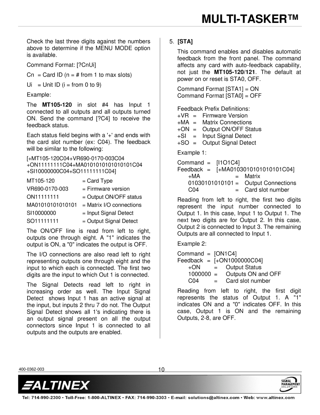
Each status field begins with a '+' and ends with the card slot number (ex: C04). The feedback will be similar to the following:
= Card Type | |
= Firmware version | |
ON11111111 | = Output ON/OFF status |
MA01010101010101 | = Matrix I/O connections |
SI10000000 | = Input Signal Detect |
SO11111111 | = Output Signal Detect |
The ON/OFF line is read from left to right, outputs one through eight. A "1" indicates the output is ON, a "0" indicates the output is OFF.
The I/O connections are also read left to right representing outputs one through eight and the input to which each is connected. The first two digits are the input to which Out 1 is connected.
The Signal Detects read left to right in increasing order as well. The Input Signal Detect shows Input 1 has an active signal at the input, but inputs 2 thru 7 do not. The Output Signal Detect shows all 1's indicating there is an output signal present on all the output connectors since Input 1 is connected to all outputs and the outputs are enabled.
5.[STA]
This command enables and disables automatic feedback from the front panel. The command affects any card with
Command Format [STA1] = ON Command Format [STA0] = OFF
Feedback Prefix Definitions: +VR = Firmware Version +MA = Matrix Connections
+ON = Output ON/OFF Status
+SI = Input Signal Detect
+SO = Output Signal Detect
Example 1: |
|
|
Command = | [I1O1C4] |
|
Feedback = | [+MA0103010101010101C04] | |
+MA | = | Matrix |
01030101010101 = | Output Connections | |
C04 | = | Card slot number |
Reading from left to right, the first two digits represent the input number connected to Output 1. In this case, Input 1 to Output 1. The next two digits are for Output 2. In this case, Output 2 is connected to Input 3. The remaining Outputs are all connected to Input 1.
Example 2: |
|
|
Command = | [ON1C4] | |
Feedback = | [+ON1000000C04] | |
+ON | = | Output Status |
1000000 | = Outputs ON and OFF | |
C04 | = | Card slot number |
Reading from left to right, the first digit represents the status of Output 1. A "1" indicates ON and a "0" indicates OFF. In this case, Output 1 is ON and the remaining Outputs,
10 |
