AMCC 9550SX-8LP manual Port 3ware 9550SX-12 Serial ATA RAID Controller

Models: 9550SX-8LP

1 40
Download 40 pages 19.67 Kb
Page 22
Image 22

Chapter 1. Installing an AMCC 3ware 9550SX RAID Controller

Note: The LED headers on the 9550SX-12 and the 9550SX-12MI are in a very similar place.

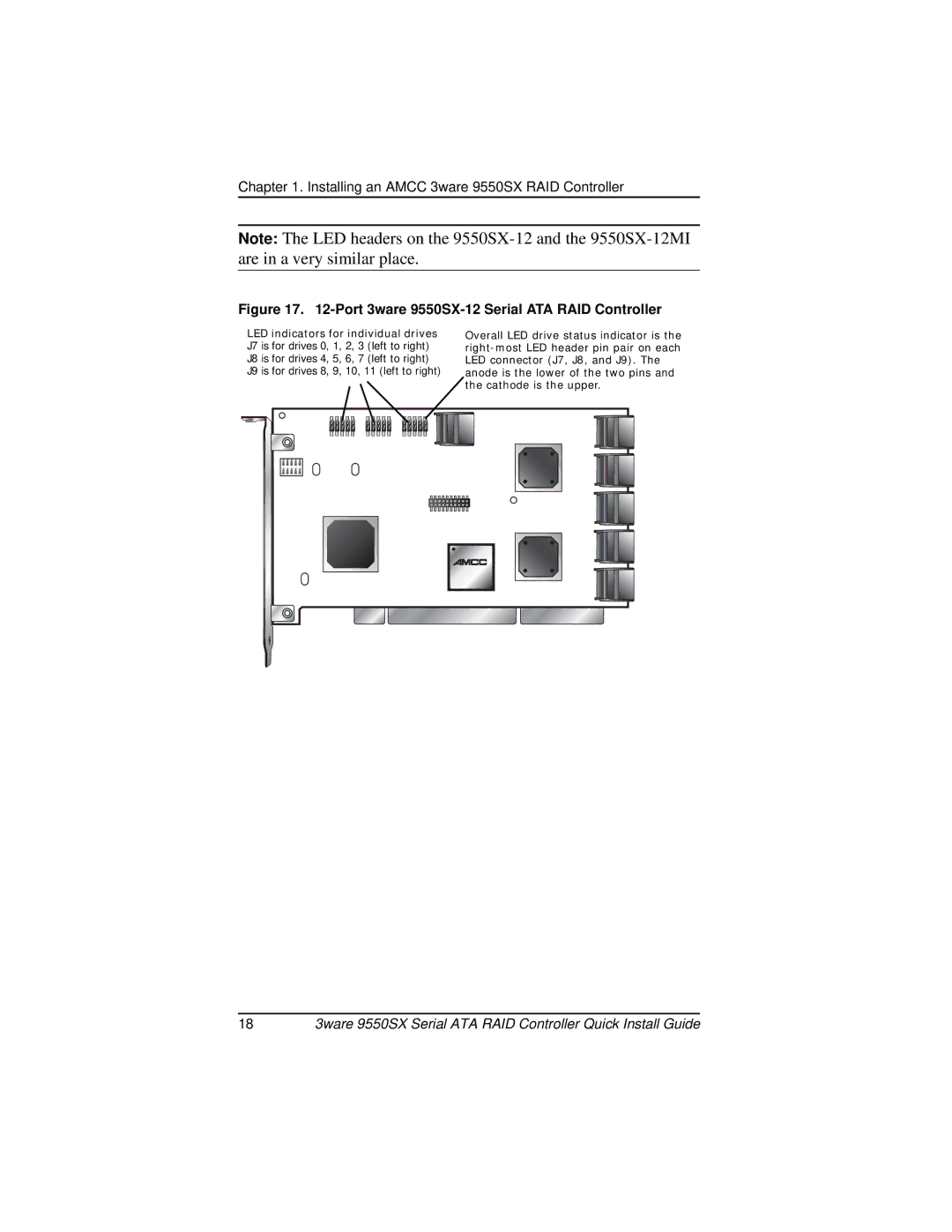
Figure 17. 12-Port 3ware 9550SX-12 Serial ATA RAID Controller

LED indicators for individual drives J7 is for drives 0, 1, 2, 3 (left to right)

J8 is for drives 4, 5, 6, 7 (left to right)

J9 is for drives 8, 9, 10, 11 (left to right)

Overall LED drive status indicator is the right-most LED header pin pair on each LED connector (J7, J8, and J9). The anode is the lower of the two pins and the cathode is the upper.

183ware 9550SX Serial ATA RAID Controller Quick Install Guide

Page 22
Image 22
AMCC 9550SX-8LP manual Port 3ware 9550SX-12 Serial ATA RAID Controller