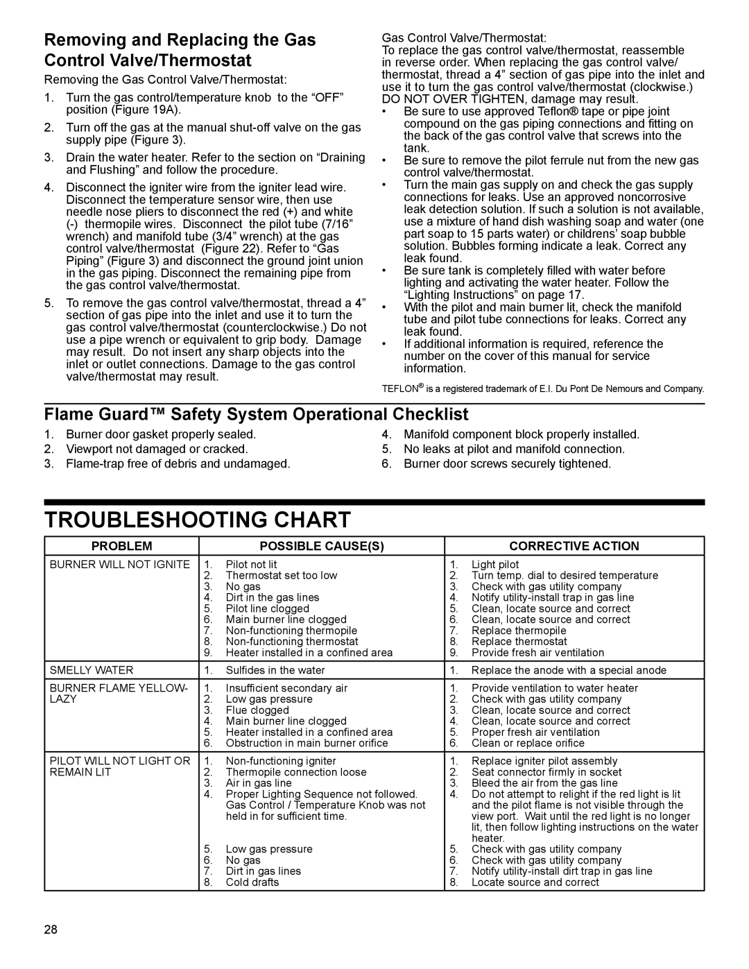
Removing and Replacing the Gas Control Valve/Thermostat

Removing the Gas Control Valve/Thermostat:

1.Turn the gas control/temperature knob to the “OFF” position (Figure 19A).

2.Turn off the gas at the manual shut-off valve on the gas supply pipe (Figure 3).

3.Drain the water heater. Refer to the section on “Draining and Flushing” and follow the procedure.

4.Disconnect the igniter wire from the igniter lead wire. Disconnect the temperature sensor wire, then use needle nose pliers to disconnect the red (+) and white (-) thermopile wires. Disconnect the pilot tube (7/16” wrench) and manifold tube (3/4” wrench) at the gas control valve/thermostat (Figure 22). Refer to “Gas Piping” (Figure 3) and disconnect the ground joint union in the gas piping. Disconnect the remaining pipe from the gas control valve/thermostat.

5.To remove the gas control valve/thermostat, thread a 4” section of gas pipe into the inlet and use it to turn the gas control valve/thermostat (counterclockwise.) Do not use a pipe wrench or equivalent to grip body. Damage may result. Do not insert any sharp objects into the inlet or outlet connections. Damage to the gas control valve/thermostat may result.

Gas Control Valve/Thermostat:

To replace the gas control valve/thermostat, reassemble in reverse order. When replacing the gas control valve/ thermostat, thread a 4” section of gas pipe into the inlet and use it to turn the gas control valve/thermostat (clockwise.) DO NOT OVER TIGHTEN, damage may result.

Be sure to use approved Teflon® tape or pipe joint compound on the gas piping connections and fitting on the back of the gas control valve that screws into the tank.

Be sure to remove the pilot ferrule nut from the new gas control valve/thermostat.

Turn the main gas supply on and check the gas supply connections for leaks. Use an approved noncorrosive leak detection solution. If such a solution is not available, use a mixture of hand dish washing soap and water (one part soap to 15 parts water) or childrens’ soap bubble solution. Bubbles forming indicate a leak. Correct any leak found.

Be sure tank is completely filled with water before lighting and activating the water heater. Follow the “Lighting Instructions” on page 17.

With the pilot and main burner lit, check the manifold tube and pilot tube connections for leaks. Correct any leak found.

If additional information is required, reference the number on the cover of this manual for service information.

TEFLON® is a registered trademark of E.I. Du Pont De Nemours and Company.

Flame Guard™ Safety System Operational Checklist

1.Burner door gasket properly sealed.

2.Viewport not damaged or cracked.

3.Flame-trap free of debris and undamaged.

4.Manifold component block properly installed.

5.No leaks at pilot and manifold connection.

6.Burner door screws securely tightened.

TROUBLESHOOTING CHART

PROBLEM


POSSIBLE CAUSE(S)


CORRECTIVE ACTION

BURNER WILL NOT IGNITE

1.

Pilot not lit

1.

Light pilot


2.

Thermostat set too low

2.

Turn temp. dial to desired temperature


3.

No gas

3.

Check with gas utility company


4.

Dirt in the gas lines

4.

Notify utility-install trap in gas line


5.

Pilot line clogged

5.

Clean, locate source and correct


6.

Main burner line clogged

6.

Clean, locate source and correct


7.

Non-functioning thermopile

7.

Replace thermopile


8.

Non-functioning thermostat

8.

Replace thermostat


9.

Heater installed in a confined area

9.

Provide fresh air ventilation

SMELLY WATER

1.

Sulfides in the water

1.

Replace the anode with a special anode

BURNER FLAME YELLOW-

1.

Insufficient secondary air

1.

Provide ventilation to water heater

LAZY

2.

Low gas pressure

2.

Check with gas utility company


3.

Flue clogged

3.

Clean, locate source and correct


4.

Main burner line clogged

4.

Clean, locate source and correct


5.

Heater installed in a confined area

5.

Proper fresh air ventilation


6.

Obstruction in main burner orifice

6.

Clean or replace orifice

PILOT WILL NOT LIGHT OR

1.

Non-functioning igniter

1.

Replace igniter pilot assembly

REMAIN LIT

2.

Thermopile connection loose

2.

Seat connector firmly in socket


3.

Air in gas line

3.

Bleed the air from the gas line


4.

Proper Lighting Sequence not followed.

4.

Do not attempt to relight if the red light is lit


Gas Control / Temperature Knob was not


and the pilot flame is not visible through the


held in for sufficient time.


view port. Wait until the red light is no longer


lit, then follow lighting instructions on the water


5.

Low gas pressure

5.

heater.


Check with gas utility company


6.

No gas

6.

Check with gas utility company


7.

Dirt in gas lines

7.

Notify utility-install dirt trap in gas line


8.

Cold drafts

8.

Locate source and correct

28

Page 28
Image 28
American Water Heater 318935-003 installation instructions Removing and Replacing the Gas Control Valve/Thermostat

318935-003 specifications

The American Water Heater 318935-003 stands out as a reliable option for residential and commercial hot water needs. Manufactured by American Water Heater Company, a brand known for its commitment to quality and innovation, this model integrates several advanced features and technologies to enhance efficiency, durability, and user experience.

One of the defining characteristics of the 318935-003 is its impressive efficiency rating. Designed with energy conservation in mind, it employs a highly efficient heating process that significantly reduces energy consumption. This not only helps in lowering utility bills for homeowners and businesses but also contributes to a more sustainable environment. The water heater meets or exceeds Energy Star guidelines, making it an eco-friendly choice.

The technology used in this model includes a state-of-the-art thermostat and advanced insulation material that ensures optimal heat retention. This dual approach minimizes heat loss, ensuring that hot water is readily available when needed while maintaining consistent temperatures. The adjustable thermostat allows users to customize settings to their preferences, thus improving comfort and efficiency.

Additionally, the 318935-003 features a robust design with high-quality materials that enhance its longevity. Its tank is constructed from durable steel, coated with a corrosion-resistant finish, which ensures that it withstands the test of time and minimizes maintenance needs. The unit is also equipped with a comprehensive safety system that includes a temperature and pressure relief valve, safeguarding against potential malfunctions.

The installation process of the American Water Heater 318935-003 is straightforward, making it accessible for both professionals and DIY enthusiasts. It is compatible with various plumbing systems and configurations, offering flexibility in installation locations. Maintenance is also user-friendly, with accessible components that allow for easy upkeep.

In summary, the American Water Heater 318935-003 embodies the ideal blend of efficiency, durability, and advanced technology. Its energy-efficient design, robust construction, and user-friendly features make it a top choice for anyone looking to fulfill their hot water requirements. Whether for a busy household or a commercial establishment, this water heater delivers consistent performance, ensuring a reliable supply of hot water year-round. Investing in the 318935-003 means investing in long-term satisfaction and efficiency, making it a wise addition to any space.