WELL-X1, WELL-X-TROL specifications
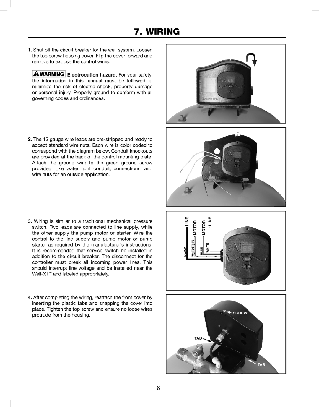
Amtrol's WELL-X1 and WELL-X-TROL series are advanced water storage and pressure tanks designed specifically for residential and commercial well water systems. These tanks are engineered to improve efficiency and reliability in water supply while providing a robust solution for various water needs.One of the standout features of the WELL-X1 and WELL-X-TROL tanks is their unique diaphragm design. Unlike other tanks that rely on air pressure for water delivery, these tanks use an internal diaphragm that separates the water chamber from the air chamber. This design minimizes the risk of waterlogging, which can lead to decreased efficiency. With a constant supply of pressurized water, users experience more stable water pressure and less frequent pump cycling, ultimately extending the lifespan of the pump system.
Another key characteristic is the tanks’ construction. Both the WELL-X1 and WELL-X-TROL are made from high-quality, heavy-duty steel that is coated with a corrosion-resistant finish. This ensures durability and extends the tanks' lifespan, making them an ideal choice for both indoor and outdoor installations. Additionally, their rolled and welded construction enhances strength, ensuring that they can withstand the rigors of continuous water storage.
The WELL-X-TROL series features an integrated pressure switch, allowing for straightforward installation and added convenience. This smart design makes it easier for homeowners to manage their well system without needing extensive modifications or adjustments. Furthermore, the tanks are available in various sizes, ranging from smaller units suitable for individual homes to larger models capable of supporting multi-family dwellings or commercial applications.
In terms of performance, the WELL-X1 and WELL-X-TROL tanks excel in maintaining optimal water pressure and reducing energy consumption. This is achieved through their innovative design that minimizes cycles, allowing the pump to operate less frequently while still delivering consistent water pressure. This efficiency not only saves homeowners money on energy bills but also minimizes wear on the pump system, resulting in fewer maintenance issues.
Overall, Amtrol's WELL-X1 and WELL-X-TROL tanks represent a significant advancement in water storage technology. Their superior construction, reliable diaphragm design, and focus on energy efficiency make them a top choice for anyone seeking a dependable solution for their well water system. Whether for residential or commercial use, these tanks offer exceptional performance and peace of mind for water management.

